www.gemu-group.com 19 / 32 GEMÜ 1434 µPos
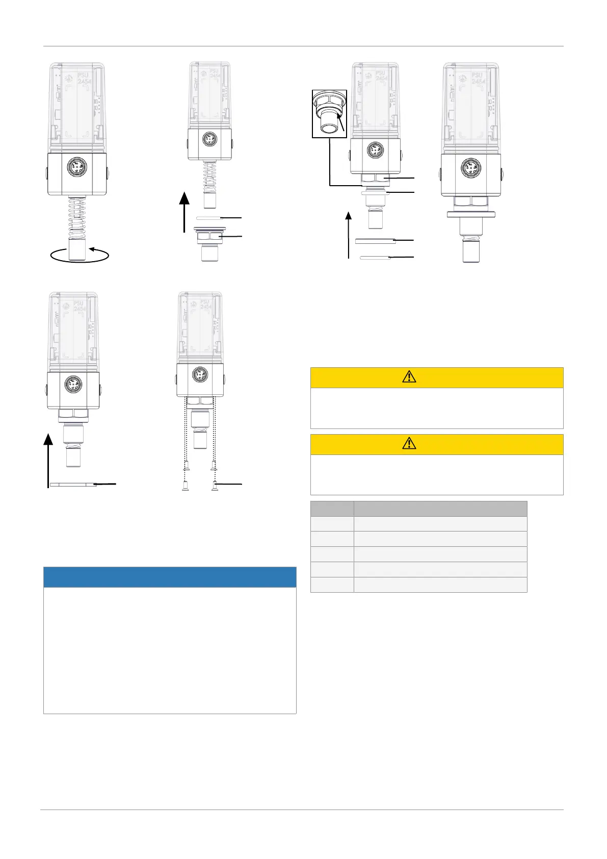
3. Tighten the operating bush
3 by turning it clockwise.
4. Affix the O-ring 5 and the ad-
apter 6.
5. Attach the flange plate 7 6. Screw the flange plate on
tight using screws 8 (1 – 1,5
Nm).
• Push in the spindle until it pushes against the spring and
then slowly release the pressure on the spring.
NOTICE
▶ For some valves (e.g. GEMÜ 650 and GEMÜ 687) it is ne-
cessary to fit a pressure disc between the threaded ad-
apter and the actuator head. This is included in the re-
quired mounting kits, sometimes with an additional O-ring
(only GEMÜ 650 with normally open and double-acting
control function – code 2+3).
▶ If the pressure disc does not have a groove for a seal, this
will already be inserted in the groove provided at the ad-
apter opening of the actuator head (e.g. GEMÜ 687 with
normally open control function – code 2).
Insert the O-ring 11 (if in-
cluded) into the corresponding
groove on the adapter 6.
If included: Push the pressure
disc 9 over the adapter 6 and
insert the O-ring 10 in the in-
tended groove of the pressure
disc.
10.3 Mounting kit assembly: With mounting bracket/
external
CAUTION
Pretensioned spring!
▶ Damage to the device.
● Slowly release the tension in the spring.
CAUTION
Do not scratch the spindle!
▶ A damaged spindle surface may cause failure of the
travel sensor.
Item Name
1 Travel sensor
2 Spindle
3 Spring
4 Operating spindle
5 Guide bush*
*Included depending on version
10 Mounting
 Loading...

