www.gemu-group.com 23 / 32 GEMÜ 1434 µPos
NOTICE
Wrong mounting kit
▶ If no initial spring tension can be felt, it may be the case
that the wrong mounting kit with too short an operating
bush has been used.
▶ If the spring locks and the positioner cannot be correctly
mounted on the valve, it may be the case that the wrong
mounting kit with too long an operating bush has been
used or that a required adapter has not been used.
▶ In both cases, check the mounting kit parts and that they
are being used correctly and in their entirety.
5. Tighten the travel sensor 4 using a suitable open-end
wrench WAF 27.
6. Connect the travel sensor 4 to the positioner 1 electrically.
7. Connect the pneumatic supply to the positioner 1 and con-
nect to the process valve 3.
11 Electrical connection
NOTICE
Risk: Electrostatic discharge
ü Destruction of electronic components
● When mounting the potentiometer, take the necessary
ESD safety precautions.
NOTICE
Risk of cable break
▶ Overtightening can result in damage to the internal
cables.
● Turn electrical connections once by max. 360°.
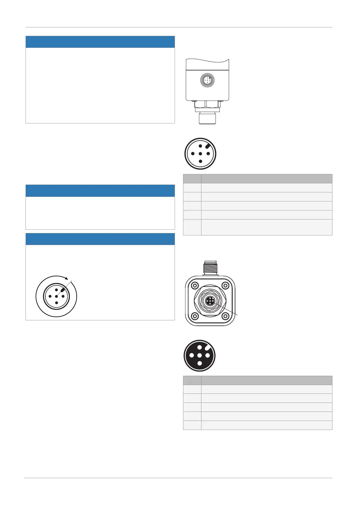
11.1 Pin assignment
Position of the connectors
Pin assignment
Pin Signal name
1 Uv, 24 V DC supply voltage
2 I+/U+, set value input
3 I-/U-, GND Uv-
4 I+/U+, actual value output (optional)
5 U, initialisation 24 V DC, started by an impulse signal
t > 100 ms (speed
-AP
function)
Version with external actual value potentiometer (code S01)
Position of the connectors
Pin assignment
Pin Signal name
1
1)
UP-, potentiometer output, supply voltage (-)
2 UPsig, potentiometer wiper voltage input
3
1)
UP+, output potentiometer supply voltage (+)
4 n.c.
5 n.c.
1) Potentiometer signal is processed internally inversed.
11 Electrical connection
 Loading...

