www.gemu-group.com18 / 32GEMÜ 1434 µPos
9 Manufacturer's information
9 Manufacturer's information
9.1 Delivery
● Check that all parts are present and check for any damage
immediately upon receipt.
The product's performance is tested at the factory. The scope
of delivery is apparent from the dispatch documents and the
design from the order number.
9.2 Transport
1. Only transport the product by suitable means. Do not drop.
Handle carefully.
2. After the installation dispose of transport packaging ma-
terial according to relevant local or national disposal regu-
lations / environmental protection laws.
9.3 Storage
1. Store the product free from dust and moisture in its ori-
ginal packaging.
2. Avoid UV rays and direct sunlight.
3. Do not exceed the maximum storage temperature (see
chapter "Technical data").
4. Do not store solvents, chemicals, acids, fuels or similar
fluids in the same room as GEMÜ products and their spare
parts.
10 Mounting
The positioner with travel sensor version 10 mm (code 010)
or 30 mm (code 030) must be mounted directly on the valve.
For this, follow the instructions in chapter 10.2 Mounting kit
assembly: Direct mounting.
The positioner with connection for an external travel sensor
(code S01) can be mounted using a mounting bracket on the
wall or in another suitable position. The external travel sensor
must be mounted directly on the valve. For this, follow the in-
structions in chapter 10.3 Mounting kit assembly: With mount-
ing bracket/external.
10.1 Preparations for mounting to the valve
1. Move the actuator A into zero position (actuator vented).
2. Remove optical position indicator 2 and / or protective cap
1 from the actuator top.
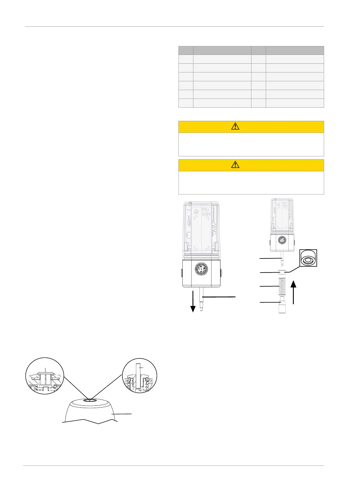
10.2 Mounting kit assembly: Direct mounting
Item Name Item Name
1 Spindle 7 Flange plate
2 Spring 8 Screws
3 Operating bush 9 Pressure disc*
4 Distance piece 10 O-ring*
5 O-ring 11 O-ring*
6 Adapter
* Included depending on version.
CAUTION
Pretensioned spring!
▶ Damage to the device.
● Slowly release the tension in the spring.
CAUTION
Do not scratch the spindle!
▶ A damaged spindle surface may cause failure of the
travel sensor.
1. Pull out the spindle 1. 2. Align the indentation of the
distance piece 4 to the spring
and push it over the spindle 1
using the spring 2 and fix it in
place using the operating bush
3.