www.gemu-group.com24 / 32GEMÜ 1434 µPos
12 Installation in potentially explosive areas
11.2 Electrical connection
● Connect the product in accordance with the pin assign-
ment.
12 Installation in potentially explosive areas
DANGER
Danger of explosion
▶ Risk of severe injury or death.
● Do not use the product in potentially
explosive zones.
● The product can control valves in po-
tentially explosive areas using special
wiring (installation of the positioner
outside the EX area).
Using technical installation measures, the product can control
valves that are located in potentially explosive areas (provided
that the valve and the travel sensor have an appropriate ap-
proval). The applicable area (zone) is dependent on the type
of ignition protection of the valve or the travel sensor.
For this, the remote mounting type (code S01) of the posi-
tioner has to be used and the electrical connection between
the travel sensor and positioner must be established using
suitable safety barriers.
For the electrical connection, use operating instructions for
GEMÜ 4232.
The product is not ATEX compliant and must therefore not be
installed or operated in potentially explosive zones.
The GEMÜ 4232 travel sensor (ATEX version) can only be
used in potentially explosive areas if used in conjunction with
an ATEX compliant safety barrier. The safety barrier needs to
have been designed specifically for use with passive resistor
elements or potentiometers and must have its own operating
instructions.
The following components have to be used for this type of op-
eration (the specified safety barriers are an example. Alternat-
ive safety barriers with similar characteristics can be used on-
site):
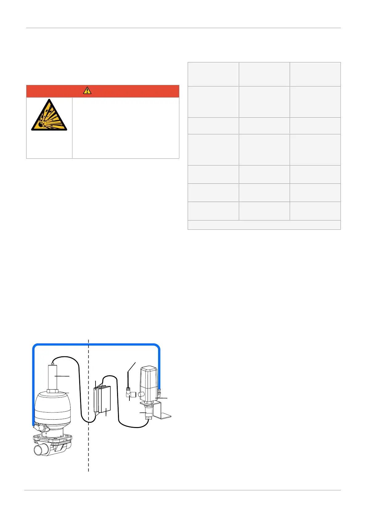
24 V DC/
set value
Potentially explosive
area
Safe area
1
4
7
6
5
2
3
Safety barriers A (5) and B (6) can alternatively also be moun-
ted in the potentially explosive area, provided that they have
their own explosion protection approval.
1. Positioner 1434
remote mount-
ing
1434000Z1... ...S01
2. Travel sensor
4232 in explo-
sion-proof
design
4232000Z14... ...00
00 X*
3. Travel sensor
mounting kit
4232S01Z…*
4. M12 connector
between travel
sensor and po-
sitioner
1219000Z0300S-
G00M0M125A
Order number:
88208779
5. Safety barrier A
(two-channel)
Safety barrier P626 Order number:
99014203
6. Safety barrier B
(one-channel)
Safety barrier P630 Order number:
99014207
7. M12 connector
X1 (optional)
1219000Z0300D-
W00M0M125A
Order number:
88208750
* Exact design dependent on valve