www.gemu-group.com 7 / 32 GEMÜ 1434 µPos
LED Colour Function
OPEN Yellow Process valve is opening/in
OPEN position
ERROR Red Error
CLOSED Orange Process valve is closing/in
CLOSED position
POWER Yellow Power
The function of the LED can differ in the case of an active ER-
ROR LED (see operating instructions).
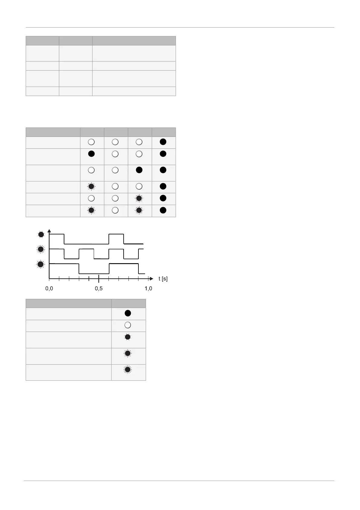
3.2.2 LED conditions
Function OPEN ERROR CLOSED POWER
Position reached
Valve in OPEN end po-
sition
Valve in CLOSED end
position
Valve OPENS
Valve CLOSES
Initialisation phase
LED condition Symbol
Lit (on)
Off
Flashes on briefly,
f=1.66 Hz; 0.30 s on/0.3 s off
Flashes slowly,
f=3.33 Hz;0.15 s on/0.15 s off
Flashes fast,
f=1.66 Hz; 0.15 s on/0.45 s off
3.3 Description
The GEMÜ 1434 μPos digital electro-pneumatic positioner is
used to control small to medium nominal size process valves
with single acting linear actuators. The solid compact housing
has a transparent cover. LEDs for status indication are integ-
rated. Due to factory preconfiguration, this product does not
require a display with operating keys. Pneumatic and elec-
trical connections are arranged so as to save space and en-
able easy access. All these features make the GEMÜ 1434
μPos a cost-effective solution for control valves with basic re-
quirements.
3.4 Function
The GEMÜ 1434 µPos digital electro-pneumatic positioner is
an intelligent digital positioner designed for mounting to pneu-
matic actuators. The product is directly mounted to the actu-
ator as standard. The travel sensor is already integrated in the
positioner.
Optionally, the product can be ordered for an external mount-
ing type, in which a separate travel sensor is connected using
an M12 connector.
The travel sensor measures the current position of the valve
and reports it to the electronic system of the product. The
electronic system then compares the actual value of the valve
with the set value specified and readjusts the valve accord-
ingly in the event of a control error.
The optional actual value output provides the valve position
currently determined (in same direction according to rule dia-
gram) as an analogue value.
For correct operation, the positioner must first be calibrated
(initialised) to the connected process valve. This is carried out
using the automatic initialisation function, which can be activ-
ated by a momentary voltage pulse at the programming input.
Once this has been carried out, the positioner automatically
switches to the normal operating mode and responds to the
specified external set value signal.
3 Product description