651
25/44
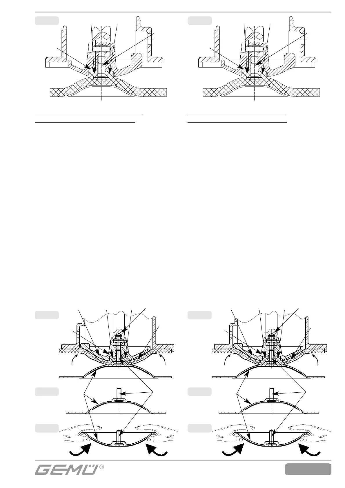
Mounting a convex diaphragm
(DN 15-25, diaphragm size 25)
1. Disassemble the actuator as described
under chapter 10.1.
2. Invert the diaphragm face manually (fig. 6,
fig. 7); use a clean, padded mat with
bigger nominal sizes.
3. Position the backing diaphragm onto the
compressor.
4. Position the diaphragm rear face onto the
backing diaphragm.
5. Screw the diaphragm face clockwise tightly
into the compressor. The diaphragm boss
must fit closely in the recess of the
compressor (fig. 8).
6. If it is difficult to screw it in, check the
thread, exchange damaged parts.
7. When clear resistance is felt turn back the
diaphragm anticlockwise until its bolt holes
are in correct alignment with the bolt holes
of the actuator.
8. Press the diaphragm face tightly onto the
backing diaphragm manually so that it
returns to its original shape and fits closely
on the backing diaphragm.
Montage der Konvex-Membrane
(DN 15-25, Membrangröße 25)
1. Antrieb demontieren wie unter Kapitel 10.1
beschrieben.
2. Membranschild von Hand umklappen
(Bild 6, Bild 7); bei großen Nennweiten
saubere, gepolsterte Unterlage verwenden.
3. Stützmembrane auf Druckstück auflegen.
4. Membranschild auf Stützmembrane auf-
legen.
5. Membranschild von Hand im Uhrzeiger-
sinn fest in Druckstück einschrauben. Der
Membrandom muss in der Druckstück-
aussparung liegen (Bild 8).
6. Bei Schwergängigkeit das Gewinde prü-
fen, beschädigte Teile austauschen.
7. Beim Verspüren eines deutlichen Wider--
stands die Membrane soweit zurück-
schrauben, bis das Lochbild der Membra-
ne mit dem Lochbild des Antriebs über-
einstimmt.
8. Membranschild von Hand fest auf die
Stützmembrane drücken, so dass sie
zurückklappt und an der Stützmembrane
anliegt.
Bild 5
Membrandom
Schraub-
pin
Druck-
stückaus-
sparung
Fig. 5
Diaphragm boss
Threaded
pin
Recess of
compressor
Bild 8
Bild 7
Bild 6
Membrandom Verbindungs-
stück
Stütz-
mem-
brane
Druckstück-
aussparung
Druckstück
Schraub-
pin
Membran-
schild
Fig. 8
Fig. 7
Fig. 6
Diaphragm boss Adapter
Backing
dia-
phragm
Recess of
compressor
Compressor
Threaded
pin
Diaphragm
face