0
1
2
4
6
8
10
2
3
4
5
6
MG 40
MG 100
MG 80
MG 50
0
1
2
4
6
8
10
2
3
4
5
6
MG 8 (0T1)
MG 8 (0TA)
MG 25
MG 10
0
1
2
4
6
8
10
2
3
4
5
6
MG 8 (0T1) + MG 25
MG 8 (0TA)
MG 10
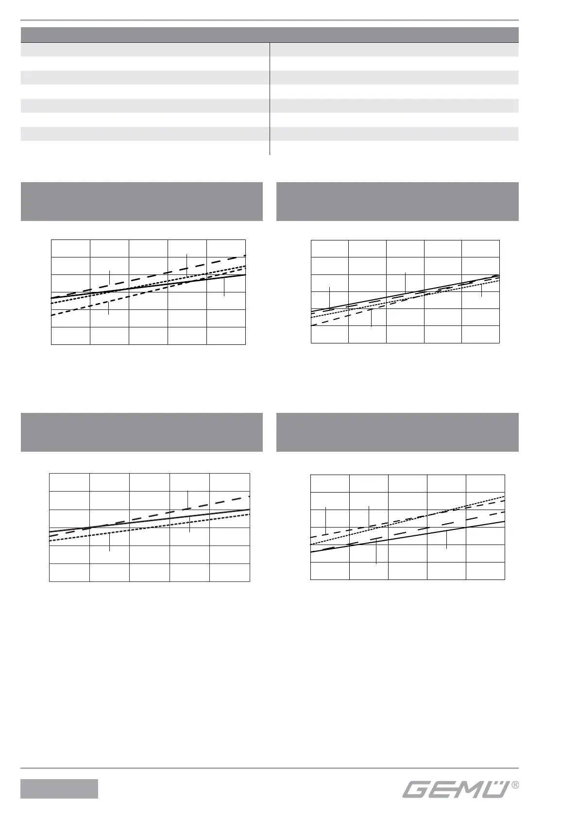
Control function 2 + 3
with elastomer diaphragm
Diaphragm size 8 to 25
Control function 2 + 3
with PTFE diaphragm
Diaphragm size 8 to 25
Operating pressure [bar]
Control pressure [bar]
Control function 2 + 3
with elastomer diaphragm
Diaphragm size 40 to 100
Control function 2 + 3
with PTFE diaphragm
Diaphragm size 40 to 100
Operating pressure [bar]
Control pressure [bar]
Operating pressure [bar]
Control pressure [bar]
The control pressure depending on the prevailing operating pressure, as shown in the dia-
gram, is intended as a guide for operating the system with low wear on the diaphragm.
Autoclavability
Actuator size 0 Standard version with autoclave capability
Actuator size 1 Standard version with autoclave capability
Actuator size 2 Standard version with autoclave capability
Actuator size 3 with special version
Actuator size 4 with special version
Actuator size 5 not possible
Actuator size 6 not possible
Actuator size 8 not possible
0
1
2
4
6
8
10
2
3
4
5
6
MG 40
MG 80
MG 100
MG 50
Operating pressure [bar]
Control pressure [bar]
32 / 52
650