3. Check if the compressor fits closely in the
guides.
4. Screw new diaphragm tightly into the
compressor manually.
5. Check if the diaphragm boss fits closely in
the recess of the compressor.
6. If it is difficult to screw it in, check the
thread, replace damaged parts (only use
genuine parts from GEMÜ).
7. When clear resistance is felt turn back the
diaphragm anticlockwise until its bolt
holes are in correct alignment with the
bolt holes of the actuator.
11.3.3 Mounting a
convex diaphragm
1. Move actuator A to the closed position.
2. Diaphragm sizes 25 - 80: Place the
compressor loosely on the actuator
spindle, fit the recesses into the
guides (see chapter 11.3.1 "General
information")
3. Check if the compressor fits closely in the
guides.
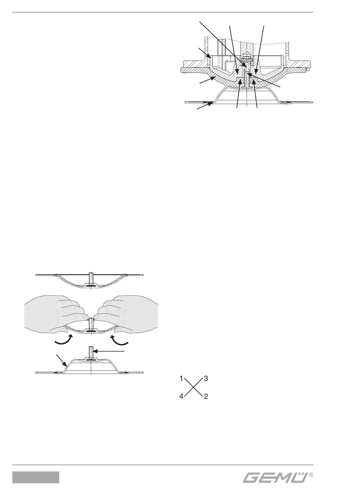
4. Invert the new diaphragm face manually; us e
a clean, padded mat with bigger nominal
sizes.
III.
I.
II.
Diaphragm face Diaphragm
pin
5. Position the new backing diaphragm onto
the compressor.
6. Position the diaphragm face onto the
backing diaphragm.
7. Screw diaphragm face tightly into the
compressor manually. The diaphragm
boss must fit closely in the recess of the
compressor.
Diaphragm boss
Recess of compressor
Com-
pressor
Adapter
Backing
diaphragm
Diaphragm face
Diaphragm
pin
8. If it is difficult to screw it in, check the thread,
replace damaged parts.
9. When clear resistance is felt turn back the
diaphragm anticlockwise until its bolt
holes are in correct alignment with the
bolt holes of the actuator.
10. Press the diaphragm face tightly onto the
backing diaphragm manually so that
it returns to its original shape and fits
closely on the backing diaphragm.
11.4 Actuator mounting on the
valve body
1. Move actuator A to the open position.
2. Position actuator A with the mounted
diaphragm 2 on the valve body 1, take
care to align the compressor weir and
valve body weir (only for diaphragm size
8).
3. Tighten bolts 18, washers 19 and nuts 20
by hand (hand tight only) (fastening
elements may vary dependent on
diaphragm size and / or valve body
version).
4. Move actuator A to the closed position.
5. Fully tighten the bolts 18 with nuts 20
diagonally.
6. Ensure that the diaphragm 2 is compressed
evenly (approx. 10-15 %,
visible by an even bulge to the outside).
7. Check tightness of completely assembled
valve.
42 / 52
650