General Information
6 Owner’s Manual for 60 Hz Synergy™ Generators
The AVR cooling air inlet includes a filter. Verify the filter
is installed and properly seated at time the unit is
installed.
Check the filter at regular maintenance intervals to verify
proper airflow.
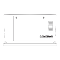
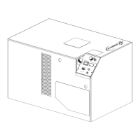
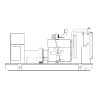
The Generator
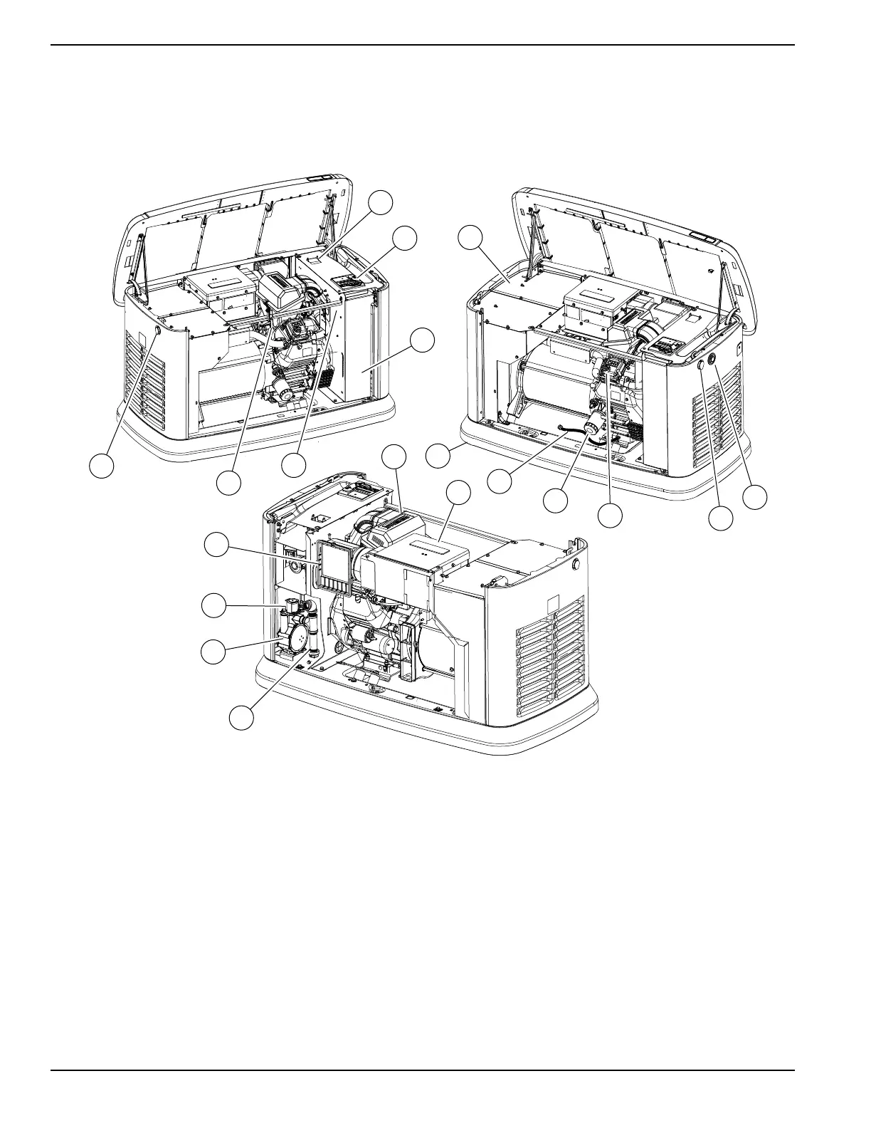
Figure 2-1. Components and Control Locations
003589
B
G
H
A
C
D
A
E
F
R
Q
P
S
N
O
L
K
J
M
A. Lock with Cover F. Oil Dipstick L. Oil Drain Hose Q. Fuel Regulator
B. Main Line Circuit
Breaker (Generator
Disconnect)
G. Exhaust Enclosure M. Composite Base R. Fuel Inlet
C. Control Panel H. Status LED Indicators N. Airbox with Air Cleaner S. AVR Air Filter
D. Battery Compartment
(Battery not supplied)
J. Oil Fill Cap O. Automatic Voltage
Regulator (AVR)
E. Data Plate Location K. Oil Filter P. Sediment Trap
 Loading...