Operation
12 Owner’s Manual for 60 Hz Synergy™ Generators
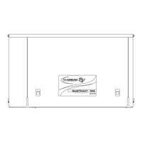
Main Line Circuit Breaker (Generator
Disconnect)
This is a 2-pole breaker rated according to relevant
specifications. See (A) in Figure 3-3.
The breaker can be locked in the OFF (OPEN) position
for security. Use an appropriately-sized padlock (not
included) with a shackle long enough to pass through
both lock tabs (B).
Figure 3-3. Main Breaker
NOTE: DO NOT lock out the MLCB during normal
generator operation. Doing so will compromise automatic
standby functionality.
LED Indicator Lights
Figure 3-4. LED Indicator Lights
See Figure 3-4. Three LEDs are visible behind a
translucent lens on the generator side panel. These
LEDs indicate the operating status of the generator.
• Green LED “Ready” light (A) is illuminated when
utility is present and the control panel button is in
the AUTO position. The LED flashes when the
automatic transfer switch converts to generator
power during a utility power outage.
• Red LED “Alarm” light (B) is illuminated when the
generator is OFF or a fault is detected. Contact an
IASD.
• Yellow LED “Maintenance” light (C) is illuminated
when scheduled maintenance is due.
NOTE: Yellow Maintenance or Warning LED may be on
at the same time as either the Red or Green LED.
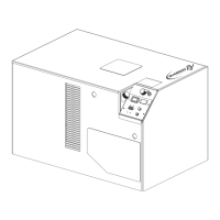
Control Panel Interface
See Figure 3-5. The control panel interface (A) is located
under the lid of the enclosure. Verify that both the left and
right side locks are unlocked before attempting to lift the
lid of the enclosure. Open the lid as directed in Opening
the Lid.
The 7.5A fuse is located beneath the rubber cover (B) to
the right of the control panel.
Verify that both the left and right side locks are securely
out of the way before closing the unit.
Figure 3-5. Generator Control Panel
All appropriate panels must be in place during any
operation of the generator. This includes operation by a
servicing technician while conducting troubleshooting
procedures.
003621
 Loading...