Do you have a question about the Generac Power Systems 5735 and is the answer not in the manual?
Directs users to the first troubleshooting path for AC output issues.
Identifies a specific AC output problem and directs to further tests.
Outlines troubleshooting steps for zero or residual AC voltage output.
Continues troubleshooting steps for low AC voltage issues.
Addresses voltage/frequency drop under load conditions.
Guides troubleshooting for lack of battery charging.
Details troubleshooting for the 10A battery charge circuit.
Provides a flowchart for diagnosing an engine that won't crank.
Outlines steps for diagnosing an engine that cranks but won't start.
Addresses issues with difficult starting or rough engine operation.
Guides troubleshooting for engines that start and then stop.
Details troubleshooting steps for a blowing 10A fuse.
Addresses generator overspeed conditions.
Troubleshoots issues where idle RPM does not reduce.
Diagnoses problems with idle RPM not increasing under load.
Guides troubleshooting for hunting or erratic engine idle.
Details how to check voltage and frequency without a load.
Describes tests for fixed excitation and rotor amp draw.
Presents results for Test 4 based on generator size.
Provides steps to check the stepper motor and its control.
Describes how to test stator windings for resistance and continuity.
Describes how to test the rotor for resistance and insulation.
Details checking voltage and frequency under load.
Details procedures for checking battery and cables, including voltage drop tests.
Covers conditions affecting starter motor performance and testing.
Describes how to test for ignition spark.
Covers checking and adjusting ignition magneto air gaps.
Provides instructions for adjusting valve clearance.
Details procedures for engine leak-down and compression testing.
Explains how to test the oil pressure switch and associated wiring.
Introduces insulation resistance testing for windings.
Details procedures for testing stator insulation to ground.
Provides specific steps for testing stator windings against ground.
Details how to perform a rotor insulation resistance test.
Provides a wiring diagram for specific models.
Presents an electrical schematic for specific models.
Provides a wiring diagram for models with hourmeters.
Presents an electrical schematic for models with hourmeters.
Provides a wiring diagram for the 17.5 kW model.
Presents an electrical schematic for the 17.5 kW model.
Provides an alternative wiring diagram for the 17.5 kW model.
Provides another alternative wiring diagram for the 17.5 kW model.
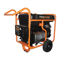
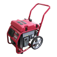
| Model | 5735 |
|---|---|
| Type | Portable Generator |
| Starting Watts | 7, 375 watts |
| Engine Displacement | 389cc |
| Fuel Tank Capacity | 7.5 Gallons |
| Starting System | Electric Start |
| Fuel Type | Gasoline |
| Weight | 192 lbs |
| Voltage | 120/240V |
| Wheel Kit | Included |
| Engine | Generac OHV |
| Outlets | Four 120V 20 Amp Outlets, One 120/240V Twist Lock Outlet |
| Outlet Types | Four 120V 20 Amp Outlets, One 120/240V Twist Lock Outlet |