Section 4 AC Diagnostic Tests
52 Diagnostic Repair Manual
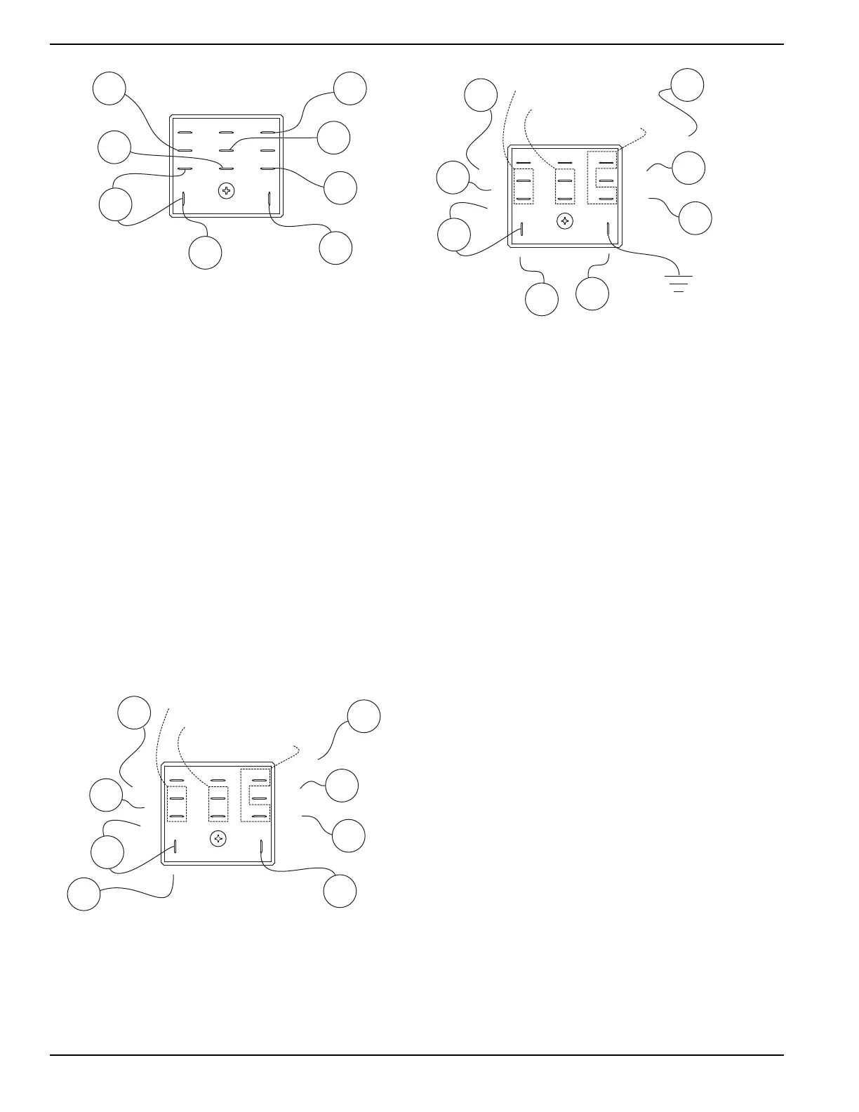
Figure 4-40. Start Stop Relay (SSR)
5. See Figure 4-40. Connect wire 15 to the SSR and
remove wire 229 from the SSR.
6. Connect a jumper lead from the terminal of the
SSR where wire 229 was just removed and to
frame ground.
a. The relay should energize closed. Visually
inspect it to see if it closes.
b. If the relay energizes closed proceed to step 4.
c. If the relay does not energize closed replace it.
7. See Figure 4-41. Remove wire 0, wire 18, wire 15,
wire 15B, wire 15, and wire 14.
8. Set DMM to measure resistance.
9. Remove jumper lead from step 6.
10. Connect meter test leads across TEST POINTS A
a. Continuity (closed) should be measured.
11. Connect meter test leads across TEST POINTS B
a. Infinity should be measured.
12. Connect meter test leads across TEST POINTS C.
a. Infinity should be measured.
13. If the SSR fails any test replace it.
Figure 4-41. Start Stop Relay (SSR) Not Energized
14. See Figure 4-42. Remove wire 229 from the SSR.
15. Connect a jumper lead from the terminal of the
SSR that wire 229 was just removed from and to
frame ground.
a. The relay should energize closed.
Figure 4-42. Start Stop Relay (SSR) Energized
16. Set DMM to measure resistance.
17. Connect meter test leads across TEST POINTS A
a. Infinity should be measured.
18. Connect meter test leads across TEST POINTS B
a. Continuity (closed) should be measured.
19. Connect meter test leads across TEST POINTS C
a. Continuity (closed) should be measured.
20. If the SSR fails any test replace it.
Results
Refer to Flow Chart.
Test 33 – Test Wire 167
Procedure
1. Set DMM to measure DC voltage.
2. See Figure 4-43. Remove the J2 connector from
the circuit board.
3. Connect the positive meter test lead to pin location
J2-5, wire 167 on the removed harness connector.
4. Connect the negative meter test lead to frame
ground.
5. Set the start-run-stop switch (SW1) to START. The
engine will crank and 12 VDC should be measured.
a. If 12 VDC is measured, stop testing.
b. If 12 VDC is not measured continue testing.
6. See Figure 4-44. Connect the positive test lead to
wire 167 at terminal block 1 (TB1).
NOTE: Where terminal block is not present, place meter
test lead on the wire at the termination point. If
necessary, use a small paper clip to probe beside the
wire so as not to damage the terminal in the connector.
SSR
15B
1413
9 10 12
5
1 2
6
4
8
229
0
18
14
15
15
15
SSR
15B
1413
9 10 12
5
1 2
6
4
8
229
0
18
14
TEST POINTS A
TEST POINTS B
TEST POINTS C
15
15
15
SSR
15B
1413
91012
5
12
6
4
8
229
0
18
14
TEST POINTS A
TEST POINTS B
JUMPER LEAD
ADDED TO GROUND
TEST POINTS C
15
15
15