Section 4 AC Diagnostic Tests
Diagnostic Repair Manual 49
NOTE: If a starting problem is encountered, check the
engine for freedom of rotation. Remove the spark plugs
and turn the crankshaft over slowly by hand, to verify that
it rotates freely.
IMPORTANT NOTE: On engines with electric starter,
rotating the crankshaft too quickly can cause arcing at
the spark plug ends. Arcing may ignite the gasoline vapor
exiting the spark plug hole.
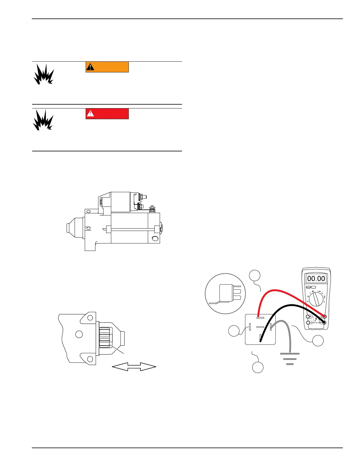
Figure 4-32. Starter Motor (SM)
Checking The Pinion
When the starter motor is activated, the pinion gear
should move and engage the flywheel ring gear. If the
pinion does not move normally, inspect the pinion for
binding or sticking.
Figure 4-33. Check Pinion Gear Operation
Test 26 – Test Starter Contactor Relay
(SCR)
Procedure
1. Set DMM to measure DC voltage.
2. Remove wire 15 from the starter contactor relay
(SCR).
3. Connect the positive meter test lead to wire 15
removed in step 2.
4. Connect the negative meter test lead to frame
Ground.
a. 12 VDC should be measured.
b. If 12 VDC is not measured on wire 15 stop
testing and repair or replace wire 15 between
the fuse (F1) and the SCR.
5. Connect wire 15 to the SCR.
6. Remove wire 13 from the starter contactor relay
(SCR).
7. Connect the positive meter test lead to wire 13
previously removed.
8. Connect the negative meter test lead to frame
Ground.
a. 12 VDC should be measured.
b. If 12 VDC is not measured on wire 13 stop
testing and repair or replace wire 13 between
the starter contactor (SC) and the starter
contactor relay (SCR).
9. Connect wire 13 to the SCR.
NOTE: Jumper leads may be used if necessary.
10. Set DMM to measure resistance.
11. Remove wire 13, wire 16, and wire 17 from the
starter contactor relay (SCR)
12. See Figure 4-34. Connect the meter leads across
terminal 87 and terminal 30 of the SCR.
Figure 4-34. Starter Contactor Relay Test
13. See Figure 4-34. Connect a jumper wire from
terminal 85 to ground.
a. The relay should energize and Continuity
should be measured.
14. Connect all wires.
WARNING
Explosion. Turn fuel supply OFF before
checking for spark. Failure to do so could
result in death or severe injury.
(000333)
(000192)
DANGER
Explosion and fire.Fuel and vapors are extremely
flammable and explosive. No leakage of fuel is
permitted. Keep fire and spark away. Failure to do
so will result in death or serious injury.