Section 4 AC Diagnostic Tests
44 Diagnostic Repair Manual
b. If continuity is not measured repair or replace
wire 0 between the C1 connector and the
ground terminal.
Results
1. Repair or replace wiring/terminals as needed.
2. If no faults are found refer to flow chart.
Figure 4-21. Brush Leads
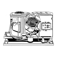
Test 13 – Check Brushes & Slip Rings
Procedure
1. Gain access to the brushes and slip rings.
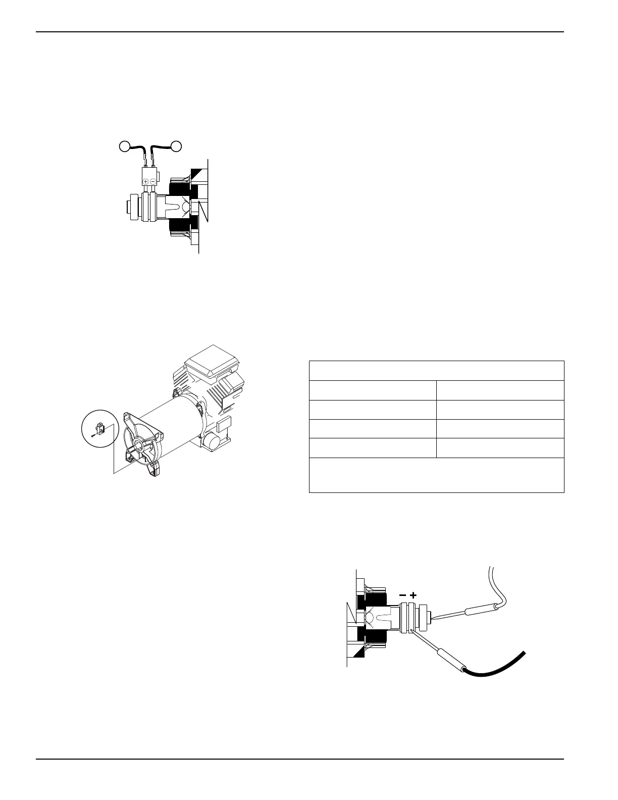
Figure 4-22. Brush Location
2. Remove wire 4 from the positive (+) brush terminal.
3. Remove the ground wire (0) from the negative (-)
brush.
4. Remove the brush holder, with brushes.
5. Inspect the brushes for excessive wear, damage,
cracks, chipping, etc.
6. Inspect the brush holder. Replace if damaged.
7. Inspect the slip rings.
a. If slip rings appear dull or tarnished they may
be cleaned and polished with fine sandpaper.
DO NOT USE ANY METALLIC GRIT TO
CLEAN SLIP RINGS. (A 400 grit wet
sandpaper is recommended).
b. After cleaning slip rings, blow away any
sandpaper residue.
Results
1. Replace bad brushes. Clean slip rings, if neces-
sary.
2. If brushes and rings are good, go to Test 14.
Test 14 – Check Rotor Assembly
Procedure
Gain access to the brushes and slip rings. Disconnect
wire 4 and wire 0 from their respective brushes and
remove the brush holder. Then, test the Rotor as follows:
1. Set DMM to measure resistance.
2. Connect the positive (+) meter test lead to the
positive (+) slip ring (nearest the rotor bearing).
3.
Connect the common (-) test lead to the negative (-)
slip ring.
4. Read the resistance of the rotor windings, in ohms.
5. Connect the positive (+) meter test lead to the
positive (+) slip ring.
6. Connect the common (-) test lead to a clean frame
ground (such as the rotor shaft).
a. Infinity should be measured.
Results
1. Replace the rotor if it fails the test.
2. If rotor checks good, perform Rotor Insulation
Resistance Test.
Figure 4-23. Testing at Slip Rings
Rotor Resistance *
kW Ohms
12.5 7.01 Ω
15.0 8.48 Ω
17.5 9.33 Ω
* Resistance values in ohms at 20 °C. (68 °F.). Actual readings
may vary depending on ambient temperature. A tolerance of
plus or minus 5% is allowed.