Section 4 AC Diagnostic Tests
Diagnostic Repair Manual 53
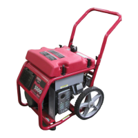
Figure 4-43. Test Wire 167, Steps 2-5
7. Connect the negative meter test lead to frame
ground.
8. Set the start-run-stop switch (SW1) to START. 12
VDC should be measured.
a. If 12 VDC is measured, replace wire 167
between TB1 and the J2 connector.
b. If 12 VDC is not measured continue testing.
9. Connect the positive test lead to wire 167
connected at the start-run-stop switch (SW1).
10. Connect the negative meter test lead to frame
ground.
Figure 4-44. Test Wire 167, Steps 6-8
11. Set the start-run-stop switch (SW1) to START. 12
VDC should be measured.
a. If 12 VDC is measured, repair or replace wire
167 between SW1 and the TB1.
b. If 12 VDC is not measured continue testing.
12. See Figure 4-45. Connect the positive meter test
to wire 15 at SW1.
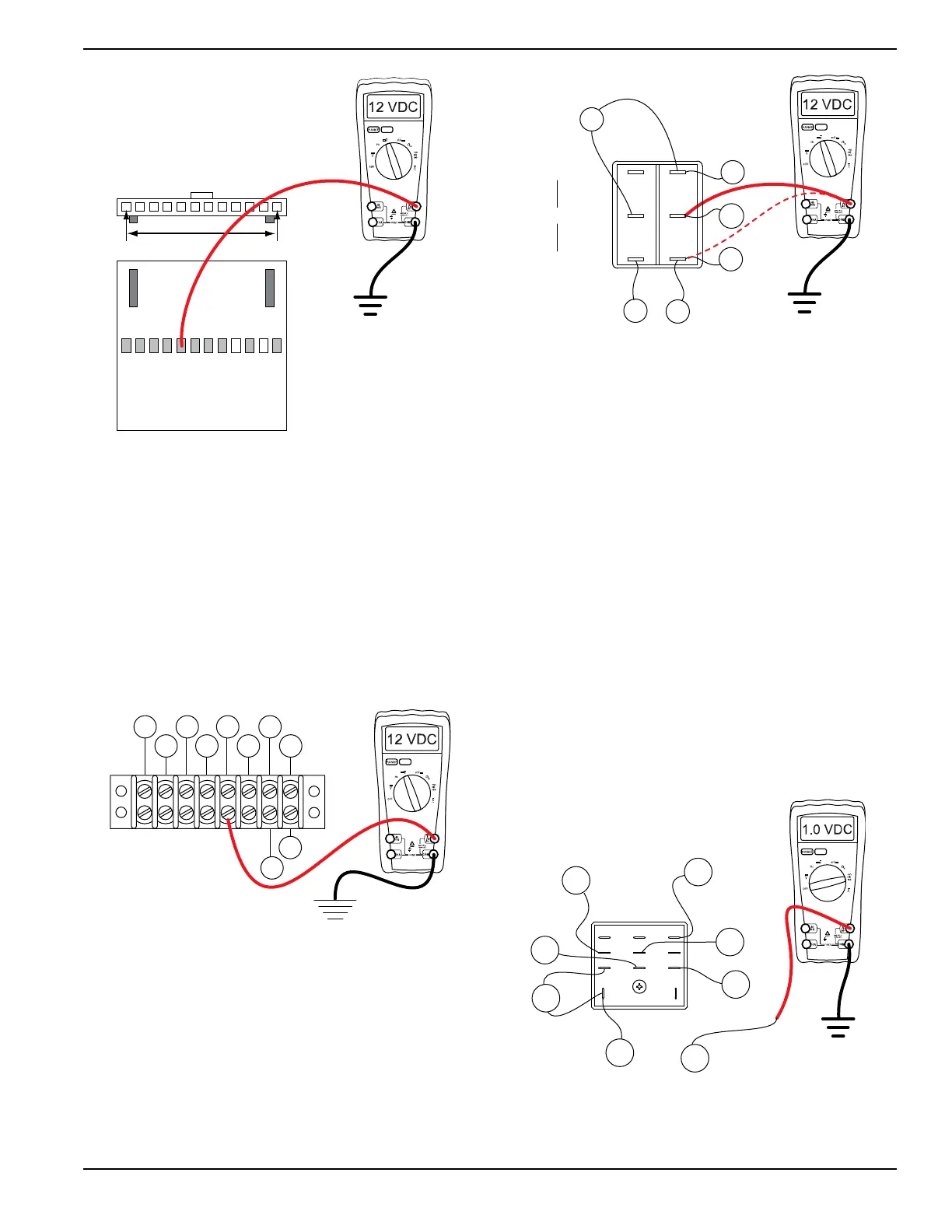
Figure 4-45. Test Wire 167, Steps 9-13
13. Connect the negative meter test lead to frame
ground. 12 VDC should be measured.
a. If 12 VDC is measured, replace SW1.
b. If 12 VDC is not measured repair or replace
wire 15 between SW1 and the Starter
Contactor Relay (SCR).
Test 34 – Test Start Stop Relay Wiring
Procedure
1. Set DMM to the diode test range.
2. Disconnect wire 229 from the start stop relay
(SSR).
3. Connect the positive meter test lead to wire 229
removed in step 2.
4. Connect the negative meter test lead to frame
ground.
5. See Figure 4-46. Set the start-run-stop switch
(SW1) to START. The meter should read
approximately 1.0 VDC.
a. If the correct voltage is indicated, stop testing.
Figure 4-46. Testing Wire 229 to Ground
6. Set DMM to measure resistance.
J2 HARNESS CONNECTOR
J2-1 J2-12
TERMINAL
BLOCK
(TB1)
86 15B
167
BLK
0 229
83
BLK
TR2
TR1
167
STOP
0
15
15
17
4
5
6
1
2
3
RUN
START
STEP 4
STEP 5
0
SSR
15B
1413
9 10 12
5
1 2
6
4
8
229
0
18
14
15
15
15