Section 4 AC Diagnostic Tests
36 Diagnostic Repair Manual
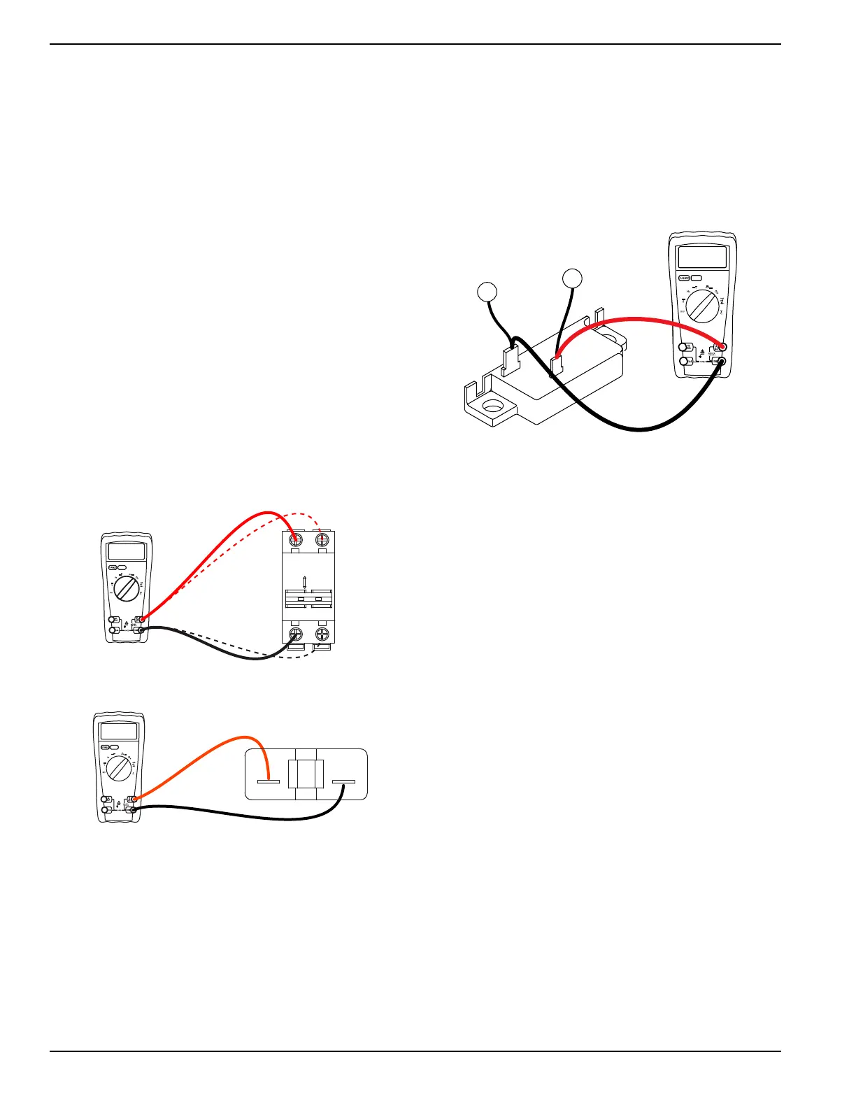
Test 2 – Check Main Circuit Breaker
Procedure
The generator has seven circuit breakers located on the
control panel. If outlets are not receiving power, verify the
breakers are set to the ON or CLOSED position.
See Figure 4-2. If a breaker failure is suspected, it can
be tested as follows:
1. Set DMM to measure resistance.
2. With generator shut down, disconnect all wires
from suspected circuit breaker terminals to prevent
interaction.
3. See Figure 4-2. With the generator shut down,
connect one meter test lead to one terminal of the
breaker and the other meter test lead to the other
terminal.
4. Set breaker to ON or CLOSED. Continuity should
be measured.
5. Set breaker to OFF or OPEN. Infinity should be
measured.
Results
1. If circuit breaker tests good, refer to flow chart.
2. If breaker tests bad, replace.
Figure 4-2. 50 Amp Breaker Test Points
Figure 4-3. 20/30 Amp Breaker Test Points
Test 3 – Test Excitation Circuit Breaker
Procedure
1. Shut down the generator and allow to cool for at
least two minutes.
2. Locate the excitation circuit breaker in the control
panel.
3. Disconnect wires from the breaker to prevent
interaction.
4. Set DMM to measure resistance.
5. Connect the DMM test probes across the circuit
breaker terminals. Continuity should be measured.
Results
1. If circuit breaker tests bad (meter reads Continuity)
proceed to Test 4 and replace the breaker after
completing Test 4.
2. If circuit breaker is good, proceed to Test 4.
Figure 4-4. Testing Excitation Circuit Breaker
Test 4 – Fixed Excitation Test/Rotor
Amp Draw Test
NOTE:
If the generator is not producing AC power, loss of
governor control may occur causing an extremely high
RPM condition (overspeed). If this condition occurs
manually control throttle (60 Hz /3600 rpm) to perform test.
Procedure
1. If testing a unit with the older style voltage regula-
tor, unplug the six pin connector from the voltage
regulator.
2. If testing a unit with the newer style voltage
regulator, disconnect wires 11S, 22S, 4, 0, 6 and
162 from the voltage regulator.
NOTE: For testing purposes the six pin connector
reference is the same as the six individual wires on the
newer style voltage regulator.
3. Connect a jumper from wire 0 to a good ground.
4. Disconnect wire 14 from resistor R1.
5. See Figure 4-5. Connect a jumper wire between
the removed end of wire 14 and wire 4 where it is
soldered at diode D1.
6. Set DMM to measure AC voltage
7. See Figure 4-6 or Figure 4-7. Disconnect wire 2
from the excitation circuit breaker and connect one
meter test lead to it.
8. Connect the other meter test lead to wire 6.
NOTE: If testing older style voltage regulator, be careful
not to damage the pin connectors with the test leads.