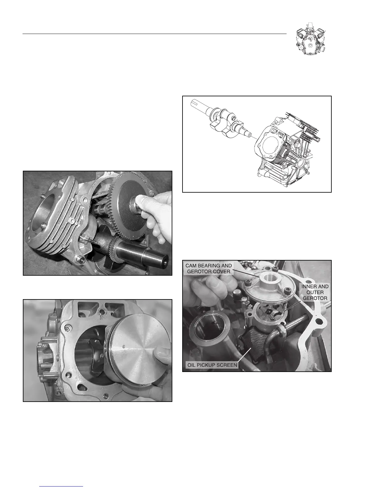
3. Rotate crankshaft and camshaft until timing marks align
and remove camshaft (Figure 9-3).
Note: If necessary, place the engine flywheel side down
to prevent tappets from catching on the camshaft.
a. Remove tappets.
Note: Remove any carbon or ridge at the top of the cylin-
der bores to prevent breaking rings when removing
piston and connecting rod assemblies.
4. Remove No. 2 connecting rod cap and push connecting
rod and piston assembly out of cylinder (Figure 9-4).
a. Reassemble cap to rod to prevent interchanging.
Figure 9-3. Remove Camshaft
Figure 9-4. Remove Pistons and Connecting Rods
5. Repeat for remaining cylinder.
6. Remove crankshaft (Figure 9-5).
Figure 9-5. Remove Crankshaft
7. Remove oil pump from crankcase cover.
Note: Clean all surfaces of gasket material. Remove oil
seals and thoroughly clean components in solvent. Orga-
nize components, keeping parts which are assemblies
together.
Figure 9-6. Remove Oil Pump
SECTION 9: ENGINE DISASSEMBLY
9-2

 Loading...