12-1
SECTION CONTENTS
PAGE
GENERAL INFORMATION.............................................. 12-1
DISASSEMBLE PISTON AND CONNECTING ROD .......... 12-1
CHECKING PISTON AND RINGS.................................... 12-1
CHECKING PISTON PIN AND CONNECTING ROD.......... 12-2
ASSEMBLE PISTON AND CONNECTING ROD ................ 12-2
ASSEMBLE PISTON RINGS TO PISTON .......................... 12-3
GENERAL INFORMATION
It is recommended that new piston rings be installed when-
ever the engine is disassembled for major servicing or overhaul,
providing that cylinder bores are within specification.
Remove any carbon or ridge at the top of the cylinder bore.
This will prevent breaking the rings when removing the piston
and connecting rod from the engine. Remove the connecting
rod cap. Push the piston and connecting rod out through the
top of the cylinder.
Measure cylinder bores before checking pistons and rings.
See Section 10. If cylinder bores are out of tolerance, it will not
be necessary to check pistons and rings since a new crankcase
and piston assemblies will be used.
If the cylinder bore is more than .075 mm (.003") oversize,
or .035 mm (.0015") out of round, it must be replaced.
DISASSEMBLE PISTON AND CONNECTING ROD
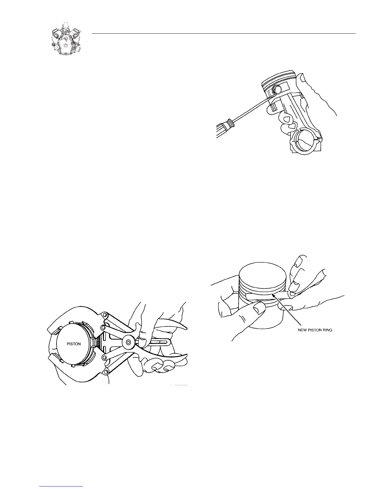
1. Remove piston rings using ring expander.
a. Then remove oil ring.
Figure 12-1. Remove Rings
2. Disassemble piston from connecting rod, Figure 12-2.
a. Remove piston pin locks.
b. Piston pin is a slip fit in piston and connecting rod.
Keep pistons and connecting rods together as an assembly.
Do not mix.
Figure 12-2. Remove Piston Pin Locks
CHECKING PISTON AND RINGS
If the cylinder is not going to be replaced and the piston shows
no signs of scoring, the piston should be checked. Carefully
remove carbon from ring grooves.
1.Check side clearance of ring grooves using new rings, Figure
12-3. If a 0.10mm (.004”) feeler gauge for the compression
rings or 0.20mm (.008”) for the oil ring can be inserted, the
ring groove is worn. The piston must be replaced.
Figure 12-3. Check Ring Grooves
2. Check ring end gap, Figure 12-4.
a. Clean carbon from end of rings and insert approximately
1" (25 mm) into cylinder.
Reject Dimension (compression rings): 0.51mm (.020")
Reject Dimension (oil rings): 1.15mm (.045")
b. If gap is less than reject dimension, remove some mater-
ial from the end of the ring to achieve the minimum gap.
3. Check piston pin bore, Figure12-5.
a. Replace if greater than 20.03mm (.7886") or if it is .01mm
(.0005") out of round.
SECTION 12: PISTON, RINGS & CONNECTING ROD INSPECTION & ASSEMBLY

 Loading...


