12-2
SECTION 12: PISTON, RINGS & CONNECTING ROD INSPECTION & ASSEMBLY
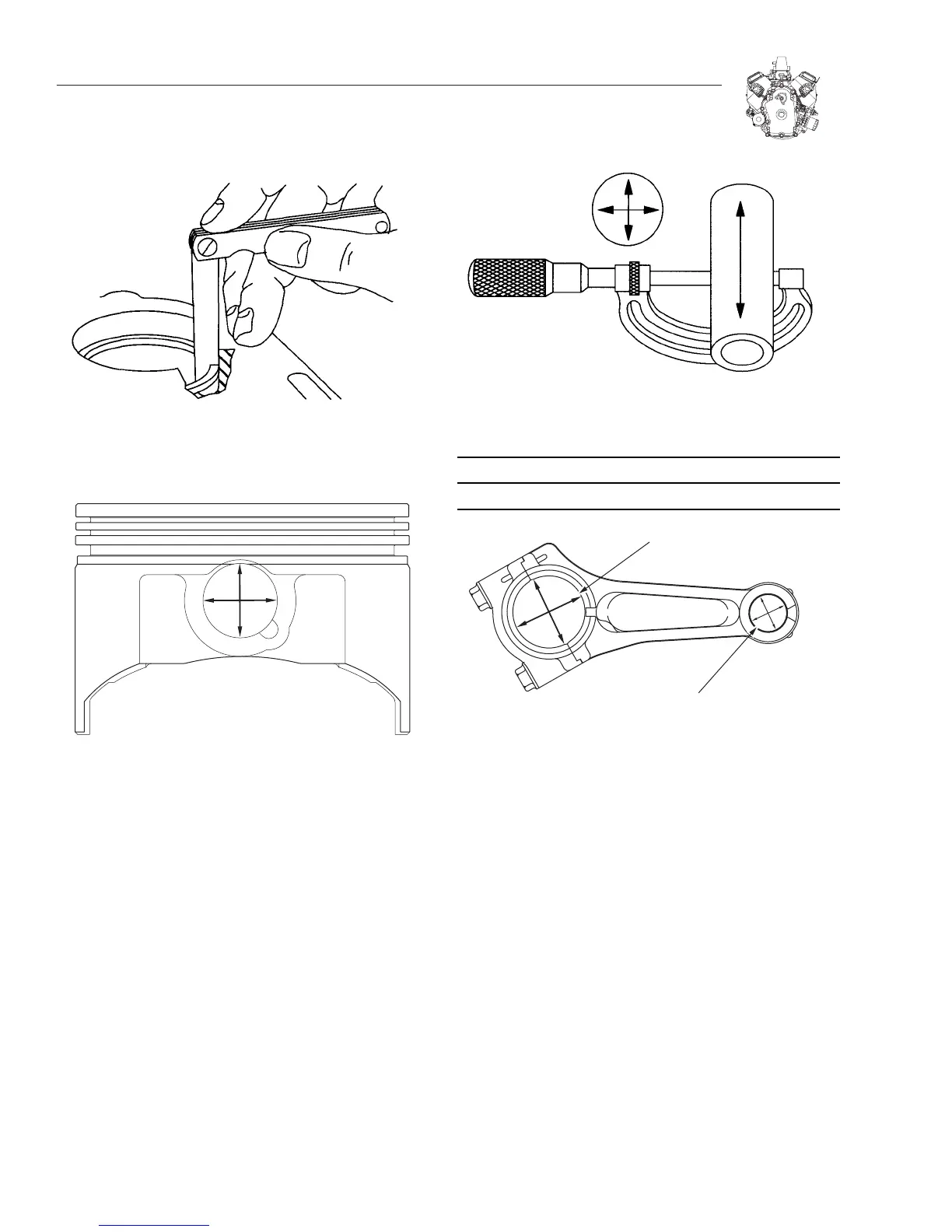
Figure 12-4. Checking Ring End Gap
Figure 12-5. Check Piston Pin Bore
CHECKING PISTON PIN AND CONNECTING ROD
1. Check piston pin, Figure 12-6.
a. Replace if less than 19.97mm (.7862") or if it is .01mm
(.0005") out of round.
2. Check connecting rod bearings.
Note: If crankpin bearing is scored or worn the connect-
ing rod must be replaced.
Figure 12-6. Check Piston Pin
CONNECTING ROD REJECT SIZE
Crankpin Bearing Piston Pin Bearing
39.09mm (1.539") 20.05mm (.7894")
Figure 12-7. Check Rod Bearings
ASSEMBLE PISTON AND CONNECTING ROD
Lubricate parts with engine oil and assemble #1 piston and
connecting rod, Figure 12-8.
1.Notch or casting mark on piston must be on flywheel side.
2.Number "1" on connecting rod must face PTO side (oppo-
site notch or casting mark on piston).
a. Install piston pin locks with needle nose pliers.
Lubricate parts with engine oil and assemble #2 piston and
connecting rod, Figure 12-9.
1.Notch or casting mark on piston must be on flywheel side.
2.Number "2" on connecting rod must face PTO side (oppo-
site notch or casting mark on piston).
a. Install piston pin locks with needle nose pliers.

 Loading...


