13-2
SECTION 13: ENGINE ASSEMBLY
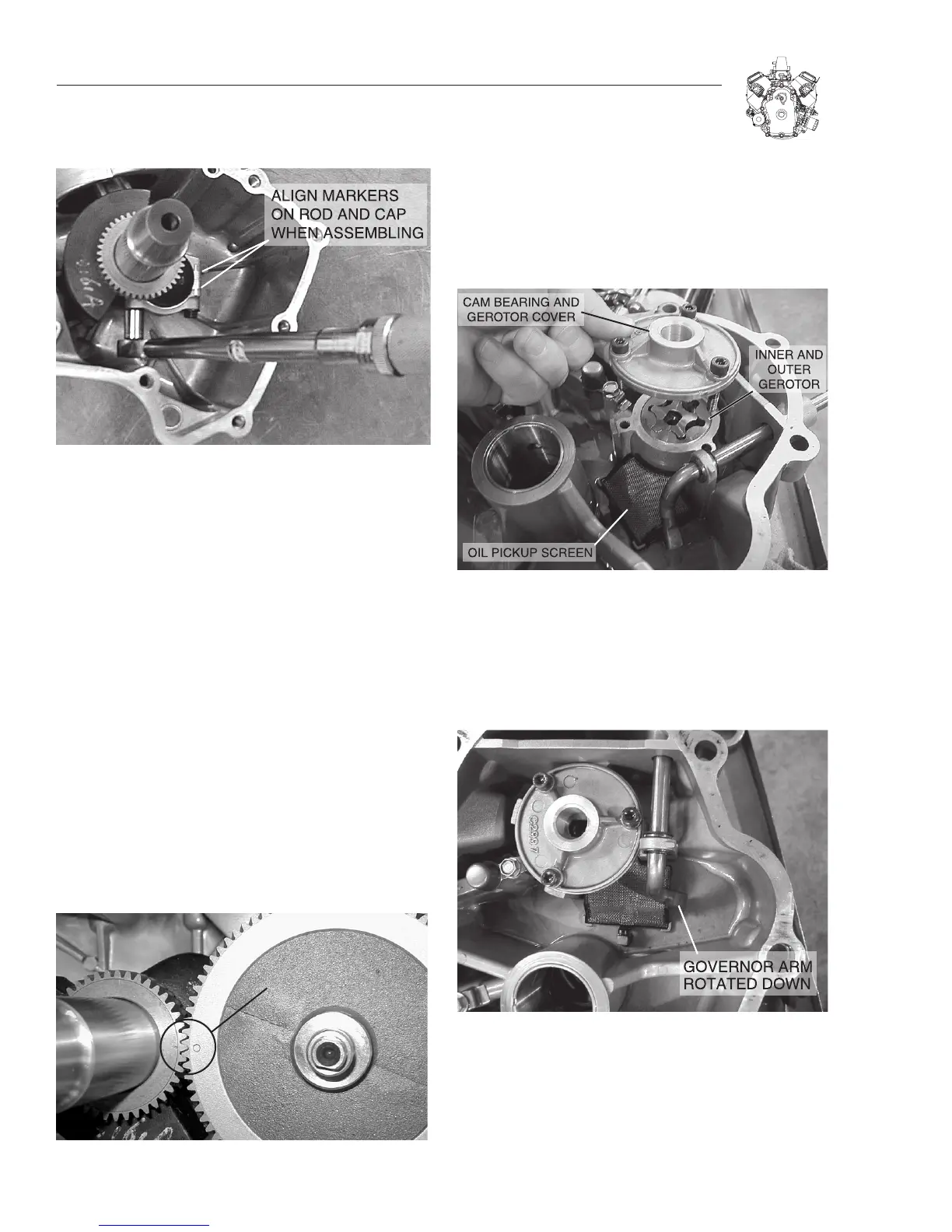
Figure 13-4. Torque Connecting Rods
5. Rotate crankshaft two revolutions to check for binding. Rod
should also be free to move sideways on crankpin.
Repeat Steps 1-5 for #2 cylinder.
Note: The number 1 on #1 connecting rod and the number
2 on #2 connecting rod must be facing PTO side.
Important: Failure to use a torque wrench can result in
loose connecting rod screws causing breakage or tight
connecting rod screws causing scoring.
INSTALL CAMSHAFT
Lubricate tappets, cam shaft journals and lobes with
engine oil.
1. Install tappets.
2. Align timing marks on cam shaft and crankshaft gear and
install cam shaft, Figure 13-5.
3. Assemble governor spool to governor shaft.
a. Make sure that spool engages flyweights.
b. Install new “O”-ring in crankcase.
Figure 13-5. Installing Camshaft
INSTALL OIL PUMP
1. Lubricate gerotor and set in place.
2. Install oil pump cover.
3. Torque screws to 12.2 Nm (9 ft. lbs.).
Figure 13-6. Installing Oil Pump
INSTALL CRANKCASE COVER
Lubricate PTO and cam gear bearing.
1. Rotate governor shaft so that the paddle rests against the
cover, Figure 13-7.
Figure 13-7. Rotating Governor Shaft
2. Install crankcase cover with new gasket.
Note: If the oil pump drive is not aligned, the cover will
not slide completely on. Turning the crankshaft may
align the oil pump drive.
3. Install governor support bracket.

 Loading...


