13-3
SECTION 13: ENGINE ASSEMBLY
a. The allen head crankcase bolt will need to be backed off.
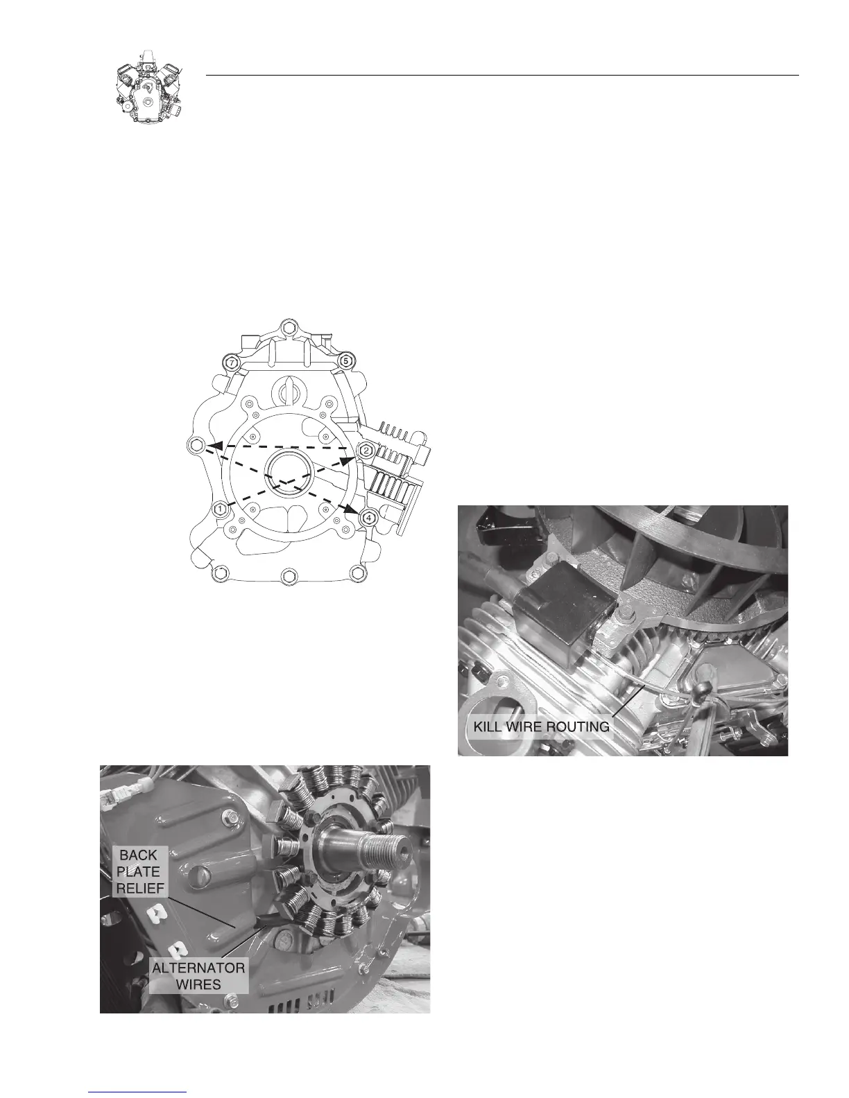
4. Torque screws in sequence shown to 47.5 Nm (35 ft. Ibs.),
Figure 13-8.
5. Check crankshaft end play. If less than 0.05mm (.002”)
there may be an assembly problem.
Figure 13-8
INSTALL ALTERNATOR AND IGNITION COILS
1. Install alternator, Figure 13-9.
a. Torque screws to 12.2 Nm (9 ft. lbs.).
Figure 13-9. Install Alternator
2. Install back plate.
a. Torque screws to 10 Nm (7.4 ft. lbs.).
Important: Route alternator wires through relief in back
plate. DO NOT pinch wires.
3. Install starter motor.
a. Torque screws to 24.4 Nm (18 ft. lbs.).
4. Assemble ignition coils to engine, Figure 13-10.
a. Mounting holes in coil are slotted. Push coil away from
flywheel as far as possible and tighten one screw to hold
coil in place.
5. Repeat for second coil.
Note: The side shown in Figure 13-10 must face up on
both coils or the engine will not function properly.
6. Install ground wire onto tab terminal on ignition coils.
Important : Make sure wires are routed over coil mount-
ing posts.
Figure 13-10. Install Coils
INSTALL BREATHER
1. Insert breather material.
2. Install breather assembly and gasket.
3. Torque bolts to 6.8 Nm (5 ft. lbs.).
INSTALL FLYWHEEL
Important: Clean flywheel and crankshaft taper remov-
ing all oil, dirt or grease.
1. Insert flywheel key into crankshaft.
2. Assemble flywheel to crankshaft.
3. Install washer and flywheel nut.
4. Torque flywheel nut to 204 Nm (150 ft. Ibs.), Figure 13-11.

 Loading...


