13-4
SECTION 13: ENGINE ASSEMBLY
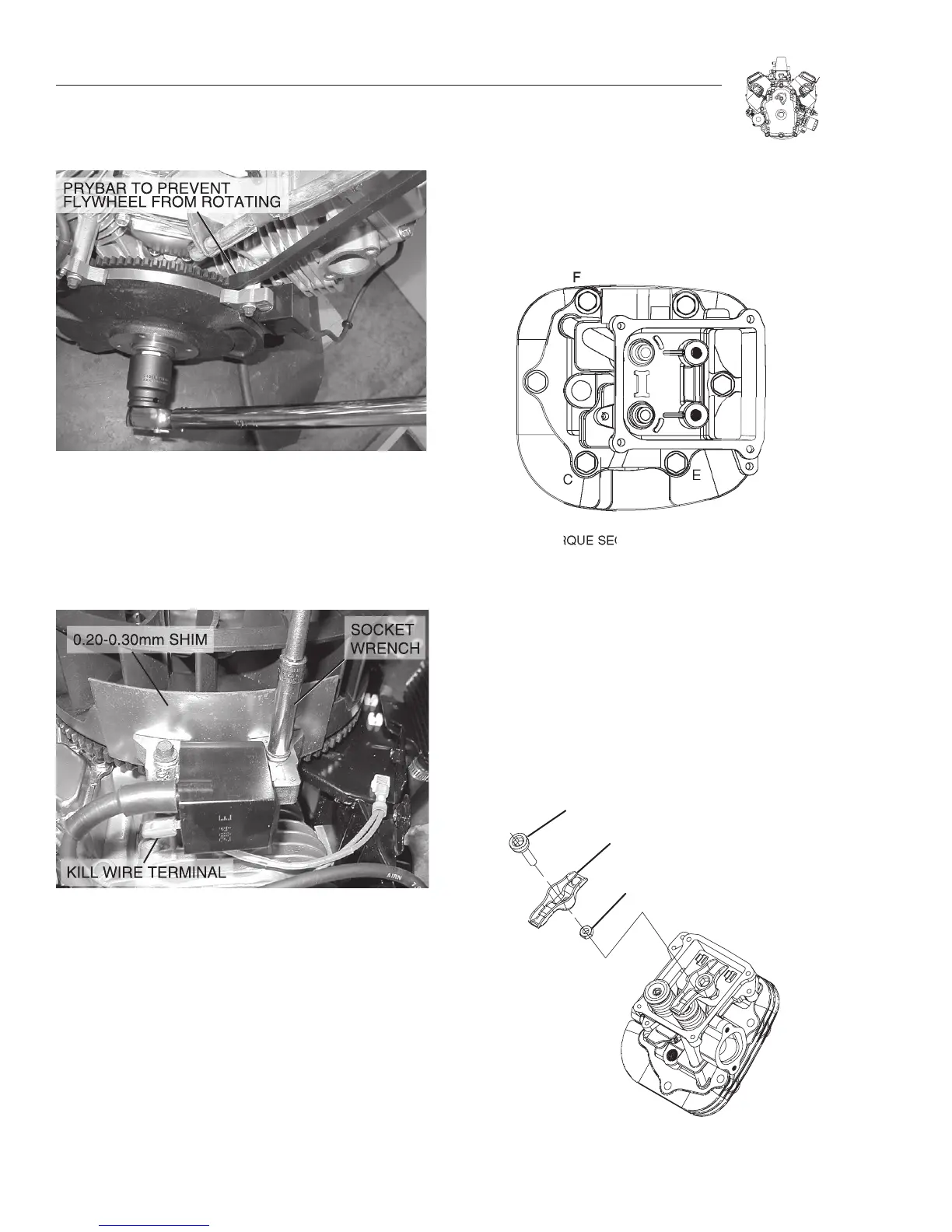
Figure 13-11. Torque Flywheel Nut
ADJUST IGNITION COIL AIR GAP
1.Rotate flywheel until magnet is under coil laminations.
2.Place 0.20-.30mm (.008"-.012") thickness gauge between
magnet and coil laminations, Figure 13-12.
Figure 13-12. Adjust Air Gap
3. Loosen mounting screw so magnet will pull coil down against
thickness gauge.
a. Torque screws to 12.2 Nm (9 ft. Ibs.).
4.Rotate flywheel to remove thickness gauge.
5.Repeat for second coil.
INSTALL CYLINDER HEADS
1. Install cylinder head with new gasket.
2. Lubricate threads of head bolts with oil.
a. Torque head bolts in sequence shown (Figure 13-13) to
29.9 Nm (22 ft. Ibs.).
3.Insert push rods into recess in tappets.
Figure 13-13. Install Cylinder Head
INSTALL ROCKER ARMS
1. Lubricate rocker arms and ball studs with clean engine oil.
2. Assemble ball studs, rocker arms, jam nuts and guide
plates to cylinder head, Figure 13-14.
a. Make sure that the push rods are in the proper location
on the tappets and the rocker arms.
Figure 13-14. Install Rocker Arms

 Loading...


