Section 5
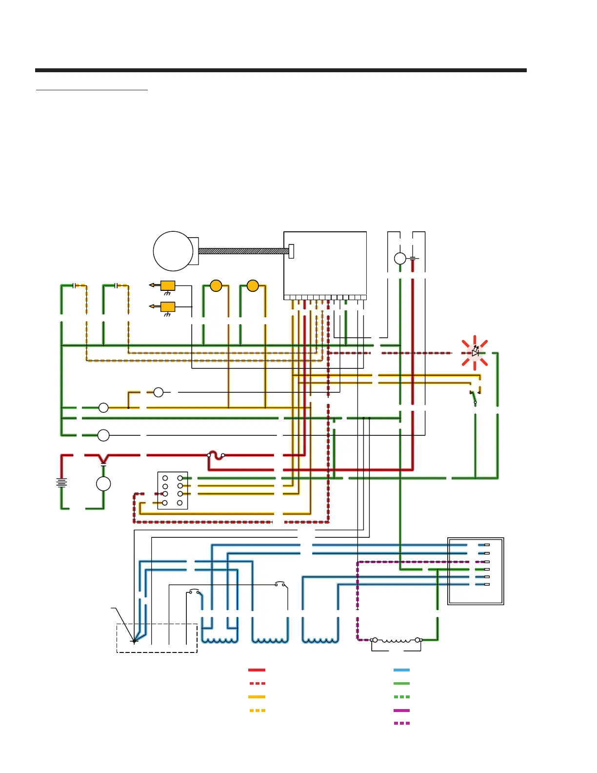
ENGINE DC CONTROL SYSTEM
Page 20
SC - STARTER CONTACTOR
TB - TERMINAL BLOCK, 4 TA B
SP2 - SPARK PLUG, CYL. 2
SP1 - SPARK PLUG, CYL. 1
LED - ALARM INDICATOR
LOP - LOW OIL PRESSURE SWITCH
SCR - STARTER CONTACTOR RELAY
SM - STARTER MOTOR
SW1 - PRIME/START- RUN-OFF SWITCH
FS - FUEL SOLENOID
FP - FUEL PUMP
F1 - FUSE, 7.5A
CH - CHOKE HEATER
CS - CHOKE SOLENOID
IMS - IGNITION MODULE STUD
IM2 - IGNITION MODULE, CYL. 2
HTO - HIGH OIL TEMPERATURE SWITCH
IM1 - IGNITION MODULE, CYL. 1
GRD1 - CONTROL PANEL GROUND
GRD2 - UNIT GROUND STUD
BA - BRUSH ASSEMBLY
CB 1 / CB 2 - SEE CHART
LEGEND
= 12 VOLTS DC
= ALARM CONTROL (PCB)
= DC CONTROL VOLTAGE (PCB)
= SHUTDOWN CONTROL (PCB)
= GROUND
= GROUND CONTROL (PCB)
= FIELD BOOST
= VOLTAGE REGULATOR
DC OUTPUT
= AC VOLTAGE
IM1
IM2
SP1
SP2
12
J1
12345678109111314
PRINTED CIRCUIT BOARD
J2
CONTROL
ACTUATOR
GOVERNOR
SW1
START
PRIME
STOP
18
17
0
SCR
56
16
F1
0131656
FP
LOPHTO
BLK RED18A
086085
REGULATOR
VOLTAGE
2
2
0
6
22S
4
11S
6
0
4
22S
11S
LED
0712
CH
CS
0
90
14
RED
BLACK
SM
SC
BATTERY
+
-
12V
SC
0
0
16
160
13
POWER WINDINGS
11
BA
33
DPE WINDING
6240
44
CB2
CB1
FIELD
BLACKRED
18
17
0
56
712
0
18
11S
22S
13
16
0
17
REMOTE
PANEL
CONNECTOR
14
712
D
E
G
F
C
B
18
17
H
A
0
GREENWHITE
0
13
712
14
0
GREEN
WHITE
0
NEUTRAL CONNECTION
AC CONNECTION
CUSTOMER
BY CUSTOMER
18 15
17
71286 90
14 85 56 0
18A
4
15
11S
0
14
0 241
FS
14
712
22
44
44
22
22S 22
00
0
+
-
CIRCUIT CONDITION – RUNNING:
With the FUEL PUMP (FP) and FUEL SOLENOID (FS) operating
and ignition occurring, the engine should start, and the START-
STOP SWITCH (SW1) is released. This voltage is delivered to the
PCB via Wire 18A to prevent STARTER MOTOR engagement above
a certain rpm.
Printed Circuit Board action terminates DC output to the STARTER
CONTACTOR RELAY (SCR), which then de-energizes to end crank-
ing. PCB action terminates DC output to the CHOKE SOLENOID
(CS).
The choke will go to a position determined by the CHOKE HEATER
(CH).
The LOW OIL PRESSURE SWITCH (LOP) is normally closed. After
startup, engine oil pressure will open the LOP.
 Loading...