Operation and Troubleshooting
8 Installation and User’s Manual for Mobile Link
Section 3: Operation and Troubleshooting
Installation
NOTE: Verify proper generator operation and
performance before adding Mobile Link
cellular during a new generator installation.
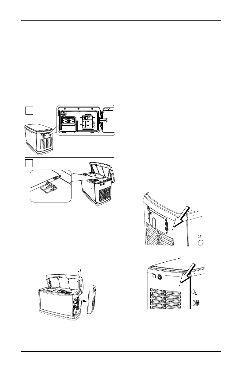
Main Circuit Breaker Locations
See Figure 3-1. Depending on your generator
model, the main circuit breaker is located
either in an external breaker box (A), or
internally near the Controller (B).
Figure 3-1. Main Circuit Breaker Locations
Installing Mobile Link Cellular
1. Unlock both locks, open generator lid, and
remove front panel.
2. See Figure 3-2. If generator is equipped
with an internal breaker near the
Controller, remove end panel from right
side. Otherwise, proceed to Step 3.
Figure 3-2. Removing End Panel
(Internal Breaker)
3. Turn generator to OFF. Remove generator
panel fuse.
NOTE: There are different Controller
configurations for various model years.
4. Turn main utility disconnect breaker in
home’s electrical panel to OFF or OPEN.
5. Using an appropriate fuse puller, remove
T1 fuse from transfer switch.
6. Disconnect battery negative (–) cable,
then positive (+) cable.
NOTE: The battery divider will need to be
removed for installation on PowerPact units.
7. If generator is equipped with an external
breaker box, remove controller sheet
metal cover and fasteners.
8. Attach provided template to position
mounting hole location in end panel.
Mounting hole location is critical for proper
operation. Mobile Link cellular unit
antenna must protrude 1 inch (2.54 cm)
above top of generator roof when
installation is complete.
NOTE: See Figure 3-3. 2013 and later models
have a pre-positioned dimple on the end panel
to mark the center of the hole.
Figure 3-3. Pre-Positioned Dimple
9. Inspect area behind external breaker box
to verify all wires are moved out of the way
to prevent damage during drilling.
002951
002729
 Loading...