Operation and Troubleshooting
Installation and User’s Manual for Mobile Link 9
NOTE: Models equipped with an internal
breaker mounted near the Controller will
already have the end panel removed at this
point. Carefully place the end panel face up on
a clean, smooth, flat surface to avoid
damaging the paint.
10. Use template provided with these
instructions to drill a 1-1/8 in. (29 mm)
hole.
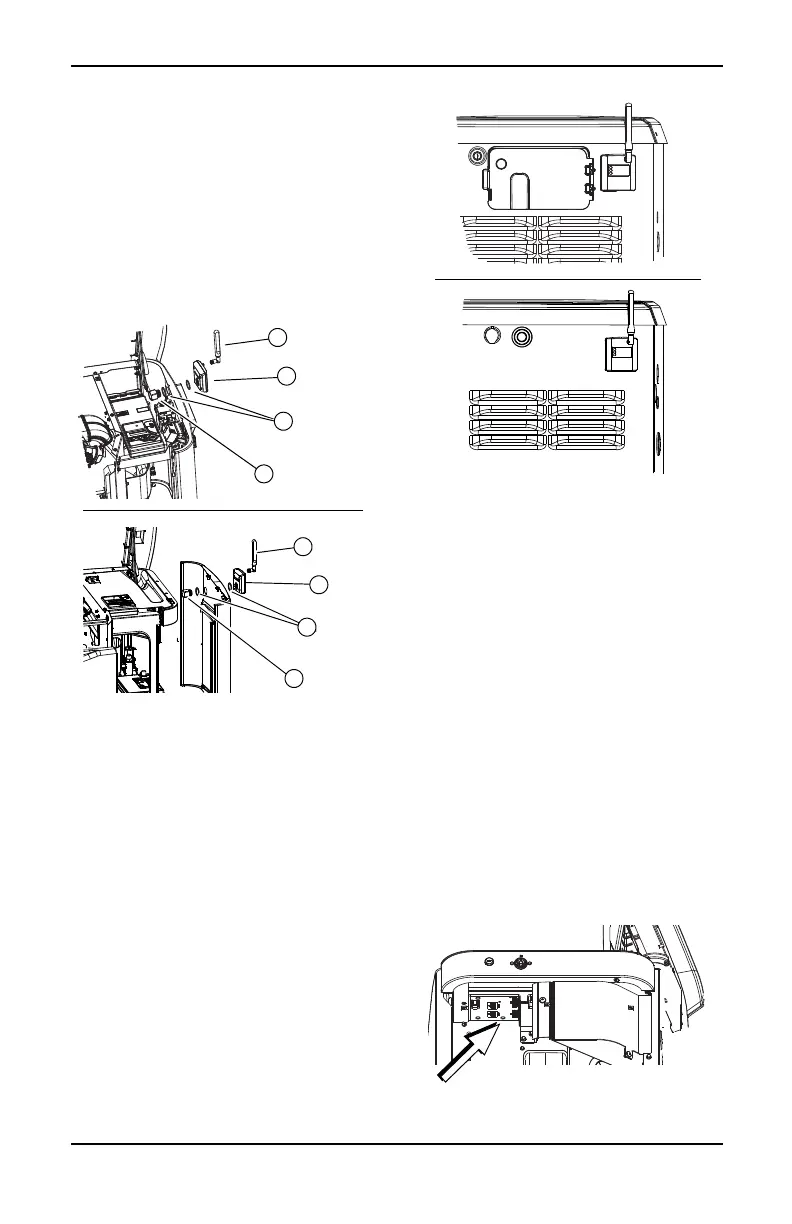
11. See Figure 3-4. Route six pin connector
through plastic fitting (A) and one green
gasket (B).
Figure 3-4. Mobile Link Cellular Installation
12. Insert plastic fitting, from inside of
generator, through newly drilled hole in
end panel. Position threaded portion of
fitting towards outside.
13. Install second green gasket (B) on outside
of end panel.
14. Thread antenna (D) into Mobile Link
cellular unit (C). Rotate antenna clockwise
until secure. Position antenna pointing up.
NOTE: Do not overtighten. Hand tighten only.
15. Insert six pin connector into Mobile Link
cellular unit. Connector will only fit one
way. DO NOT force into place.
16. See Figure 3-5. With plug installed, tighten
plastic fitting and draw Mobile Link cellular
unit to generator wall. Do not overtighten.
Position Mobile Link cellular unit with
antenna facing upwards.
Figure 3-5. Mobile Link Cellular In Place
NOTE: Hold Mobile Link cellular unit firmly
and tighten nut during installation to avoid
damage to unit wiring harness.
17. Route wire harness to back side of
controller. Wherever possible, bundle
harness with other wire looms to provide
additional support.
NOTE: On 2008 Home Standby Units only,
remove fasteners that secure controller.
18. Locate accessory port. Accessory port is
an eight-pin connector on underside of
controller.
• On models equipped with an external
breaker box, lift controller to gain
access to accessory plug location.
•See Figure 3-6. On models equipped
with an internal breaker mounted near
the controller, accessory port is visible
from the battery compartment when
end panel is removed.
Figure 3-6.
Accessory Port (Internal Breaker)
002731
 Loading...