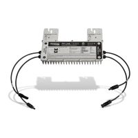
Installation Manual for PV Link 7
Installation Design
Section 3: Installation Design
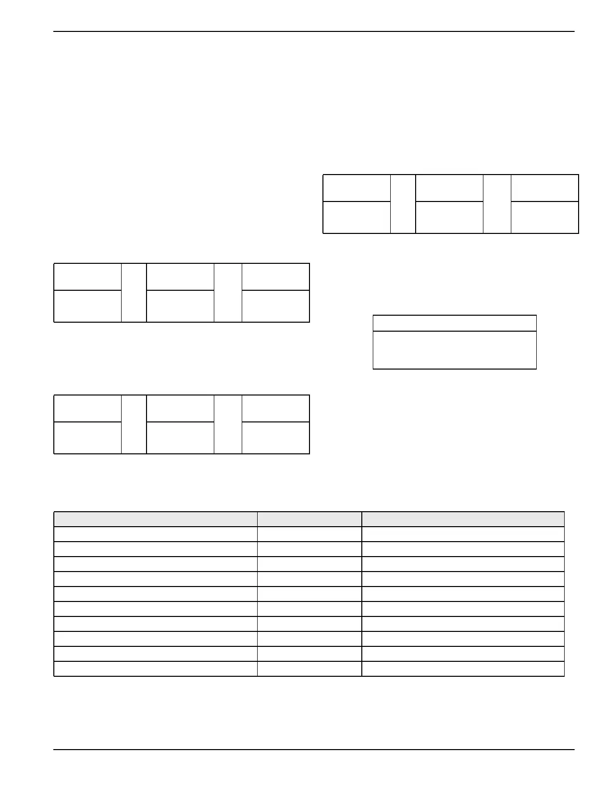
Installation Design Worksheet
Use this worksheet to determine the maximum number of
PV modules of a given type that can be connected to a
PV Link.
NOTE: Fewer PV modules can be used as long as the
minimum MPPT input voltage is met.
1. Calculate an adjusted open circuit voltage (VOC)
for the module being installed using the applicable
NEC cold factor from Table 1: NEC Cold Factor
Conversion.
NOTE: The temperature correction factor listed on the
module nameplate can be used if available.
Panel
VOC
X
NEC Cold
Factor
=
Adjusted
VOC
2. Divide the PV Link Max VOC by the Adjusted VOC
from step 1 and round down to determine the num-
ber of panels that can be connected in series to the
PV Link without exceeding the open-circuit voltage
limit.
PV Link Max
VOC
÷
Adjusted
VOC
=
VOC
Limit Result
420 V
3. Divide the PV Link voltage at maximum power
(VMP) by the panel VMP and round down to deter-
mine the number of panels that can be connected
in series to the PV Link without exceeding maxi-
mum power voltage
PV Link Max
VMP
÷
Panel
VMP
=
VMP
Limit Result
360 V
.
4. Compare the results from step 2 and step 3 and
choose the smaller number. Round down to the
nearest integer and record it below. This is the
maximum number of modules of this type that can
be connected to the PV Link given the specified
NEC cold factor.
Maximum Panels per Substring
Table 1 - NEC Cold Factor Conversion
Minimum Temperature (°F) NEC Cold Factor Minimum Temperature (°C)
49 to 41 1.08 9 to 5
40 to 32 1.10 4 to 0
31 to 23 1.12 -1 to -5
22 to 14 1.14 -6 to -10
13 to 5 1.16 -11 to -15
4 to -4 1.18 -16 to -20
-5 to -13 1.20 -21 to -25
-14 to -22 1.21 -26 to -30
-23 to -31 1.23 -31 to -35
-32 and below 1.25 -36 and below