Owner’s Manual for PV Link 13
Mounting and Connecting
2017 and 2020 NEC Compliant Systems
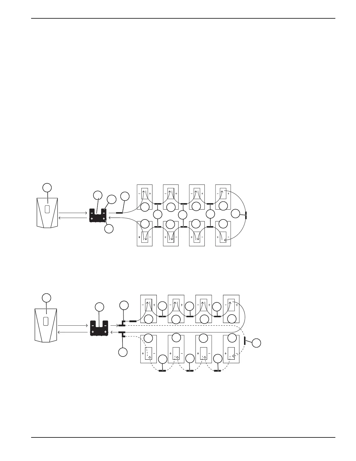
For NEC 2017 and 2020 NEC compliant systems, con-
nect the string PV modules in a series using one Gen-
erac SnapRS device per module.
NOTE: Install SnapRS devices prior to securing PV
modules to the racking.
To install SnapRS devices:
1. See Figure 5-4. Connect one SnapRS device (C)
to the negative (-) lead of each PV module (D).
2. Connect the modules in series with the SnapRS
devices installed in-line between modules by con-
necting the positive lead of each module to the
SnapRS device already installed on the negative
lead of the next PV module in the series.
3. Connect the PV string positive lead to PV Link (B)
at the location marked PV Substring Input + (F).
See Component Locations for more information.
4. Connect the PV string negative lead with its con-
nected SnapRS device to PV Link (B) at the loca-
tion marked PV Substring Input - (E). See
Component Locations for more information.
5. Secure the SnapRS devices to the racking or mod-
ule frame using zip ties or a similar fastener.
6. Make a string map using the PV Link peel-and-
stick serial number stickers and record in Table 1:
Generac PV Link Important Information the fol-
lowing information:
• Each Generac PV Link serial number
• Each Generac PV Link RCP number
• Number of parallel strings
• SnapRS devices per string
• SnapRS DoM
A Generac PWRcell Inverter
B Generac PV Link
C SnapRS Device
D PV module
E PV Substring Input -
F PV Substring Input +
010028
B
C
C
C
C
C
D
D
D
D
D
D
D
D
A
E
F
Figure 5-4. Single-String PV Array with Generac SnapRS™ Device
NOTE: See Figure 5-5. When dual strings are connected in parallel, each string must use the same number of the
same type of PV modules, and there must be one SnapRS device for each module in the array.
A Generac PWRcell Inverter
B Generac PV Link
C SnapRS Device
D PV Module
E MC4 Y Splitter
C
010029
C
E
E
C
C
C
C
C
C
B
A
D
D
D
D
D
D
D
D
Figure 5-5. Parallel-Input PV Array with Generac SnapRS™ Devices