MAKE SURE THE MACHINE HAS BEEN TURNED OFF AND UNPLUGGED FROM THE POWER SOURCE BEFORE PERFORM-
ING ANY MAINTENANCE OR ADJUSTMENTS.
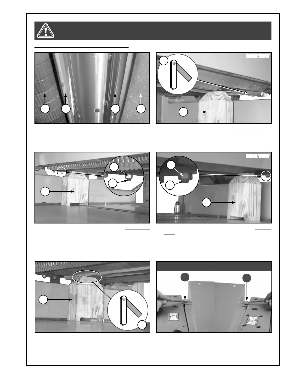
ADJUSTING THE INFEED & OUTFEED ROLLERS
1. Begin by take note of all the components in order
to make required adjustments: A infeed roller; B
chipbreaker; C cutter head with knife/insert; D out-
feedroller.
2. Place the gauge block E under the knife/insert C,
adjust the table height until you can only slide a
0.02” feeler gauge F between the block and the
cutter. Once finished, do not move the height of the
table.
A B
C
D
E
F
ADJUSTING THE CHIPBREAKER
3. Place the block E under the end of the infeed roller
A as shown. Loosen the nut G, turn the screw H until
the roller touches the top of the block, and then re-
tighten the nut G. Repeat for the other end.
4. Place the block E under the end of the outfeed
roller D. Loosen the nut I, turn the screw J until the
roller touches the top of the block, and then re-
tighten the nut I. Repeat for the other end.
E
E
G
H
I
J
1. Place the block E under a knive/insertion and ad-
just the table height until you can slide only a 0,004”
feeler gauge K between the block E and the knive/
insertion. Then place the block under the chip-
breaker B.
E
K
2. Remove the dust chute, remove the two bolts L with
a 10 mm wrench, and then lift the chip deflector
cover in order to access the cutter head.
L
L
LEFT SIDE RIGHT SIDE
REAR VIEW
REAR VIEW
17