Do you have a question about the Genie GCG350 and is the answer not in the manual?
Ensure proper ceiling support for the power head unit.
Verify secure wall structure for header bracket attachment.
Confirm clear mounting points for the Safe-T-Beam® system.
Check door material for need of additional bracing support.
Ensure a suitable power outlet is accessible near the mounting area.
Securely disable any existing door locks to prevent damage.
Confirm the garage door operates smoothly and is properly balanced.
Evaluate the need for an emergency release kit if no separate entry exists.
Security system changing access codes with each use.
Remote for operating one, two, or three garage doors.
Inside control with optional light and security features.
Stops/reverses door if beam is broken by an object.
Stops/reverses door on contact with an object.
Opens closing door if it fails to close completely.
Adjustable open/close force settings for safety.
Stops/reverses door if closing relay malfunctions.
Stops/reverses door if STB system has issues.
Provides light when door is activated, turns off after 5 mins.
Manually releases door from operator for power failure.
Single-button and multi-button remote control units.
Entrapment warning label and safety brochure.
Wall controls, STB sensors, wire, and staples.
Components for 1-piece and 3-piece rail assemblies.
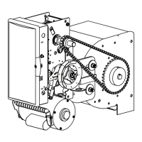
Parts list for the main power head assembly.
General safety information and hazard definitions.
Identifying, arranging, and clamping rail sections.
Securing the rail strap to the rail assembly.
Inserting the carriage slide into the rail.
Connecting the rail assembly to the power head.
Installing the emergency release cord, knob, and tag.
Mounting and positioning limit switches on the rail.
Connecting limit switch wires to the power head terminals.
Crucial safety instructions to prevent injury during installation.
Steps to find the correct location for the header bracket.
Instructions for securely attaching the header bracket.
Finding and attaching the door bracket to the garage door.
Positioning the rail/power head assembly before ceiling attachment.
Attaching mounting straps and securing the power head to the ceiling.
Setting the correct height for the emergency release knob.
Steps for attaching and connecting door arms for sectional doors.
Steps for attaching and connecting door arms for one-piece doors.
Marking and attaching the STB sensor/source brackets.
Placing the STB source and sensor modules onto brackets.
Routing and connecting the STB system wires.
Fastening STB wires with staples and connecting them.
Ensuring proper alignment and lens height before powering on.
Selecting a suitable and safe location for the wall control.
Connecting wires and attaching the wall control to the wall.
Steps for connecting using a standard grounded plug.
Instructions for permanent wiring by an electrician.
Verifying STB alignment after power connection.
Setting the open and close limit switches for the door travel.
Setting the force required for the door to open.
Setting the force required for the door to close.
Verifying the door reverses upon contact with an obstacle.
Troubleshooting and adjusting if the door doesn't reverse correctly.
Steps for programming and using a single-button remote.
How to program and use multi-button remotes.
Erasing all programmed remote controls from the operator.
Steps for replacing the battery in the remote control.
Attaching the visor clip to the remote control.
Recommendations and steps for installing the light bulb.
Steps for installing the protective lens for the light.
Key safety guidelines for operating and maintaining the opener.
Regular checks for door springs, balance, contact reverse, and STB system.
Introduction to the STB system self-diagnostic troubleshooting chart.
Diagnosing issues when the operator doesn't run or move the door.
Addressing problems with door travel limits and stopping.
Resolving problems with remote operation, range, and noise.
Diagnosing and resolving Safe-T-Beam® system errors.
Visual representation of the electrical connections for the operator.
Regulatory compliance statements for transmitters.
Details on what parts and for how long the product is covered.
Procedures for obtaining warranty service via DIY or dealers.
What the warranty does not cover and its limitations.
| Type | Chain Drive |
|---|---|
| Horsepower | 1/2 HP |
| Frequency | 60 Hz |
| Security Light | Yes |
| Voltage | 120V |
| Security | Intellicode rolling code technology |
| Motor Type | AC |
| Drive System | Chain |
| Speed | 7 inches per second |
| Battery Backup | Not included |
| Max Door Height/Lift Capacity | 7 ft (extendable to 8 ft with extension kit) |