Do you have a question about the Genie GCL-J&H 1/2HP and is the answer not in the manual?
| Horsepower | 1/2 HP |
|---|---|
| Drive Type | Chain Drive |
| Safety Sensors | Yes |
| Speed | 7 inches per second |
| Voltage | 120V |
Essential safety guidelines and checks before operating the door.
List of factors to consider before selecting an operator for a specific job site.
Requirements for fail-safe external reversing devices for momentary contact operation.
Table detailing square footage capacities for rolling steel doors based on gauge and type.
Table detailing square footage capacities for sectional doors by series and construction.
Crucial safety and procedural guidelines to follow during installation to prevent severe injury or death.
Instructions for installing the operator on rolling steel doors.
Details the procedure for mounting the operator on the front of the hood.
Step-by-step guide for installing the drive chain and sprockets.
Procedure for mounting the operator to the wall for rolling steel doors.
Instructions for installing the operator on sectional doors.
Procedure for connecting the operator to the door shaft using a chain.
Specific steps for attaching the sprocket to a hollow counterbalance door shaft.
Specific steps for attaching the sprocket to a solid counterbalance door shaft.
Procedure for installing an optional chain spreader bracket for tensioning.
Instructions for routing and installing the hand chain and keeper.
Details how to adjust the operator's friction style clutch for proper operation.
Step-by-step guide for connecting the main line voltage power to the operator.
Instructions for connecting low voltage control circuit wires for wall controls, timers, etc.
Diagram illustrating wiring connections for various control devices and inputs.
Guidelines for locating and wiring wall control stations.
Installation of optional interlock switches for rolling steel doors with locks or pass doors.
Installation of optional interlock switches for sectional doors with locks or pass doors.
Wiring instructions for monitored photocell systems, including Safe-T-Beams®.
Wiring instructions for standard commercial non-monitored photocells.
Procedure for installing sensing edge devices, including wired and wireless types.
Instructions for connecting an external radio receiver to the operator.
Procedure for connecting the motor harness and applying power.
Overview of the control panel features, keys, and display functions.
Procedure to set the correct direction for door opening and closing.
How to adjust the operator's braking rate for smooth deceleration.
Instructions for setting the upper and lower travel limits for the door.
Procedure to reset the previously set travel limits.
Adjusting the limit overrun for a proper door seal against the floor.
Configuring the operator for constant or momentary contact operation modes.
Instructions for adding a new radio transmitter to the operator.
Procedure for removing a specific radio transmitter from the operator.
Procedure for removing all programmed radio transmitters from the operator.
Setting a programmable mid-stop point for opening the door.
Procedure to reset the Maximum Run Timer (MRT) after adjustments.
Configuration and calibration of monitored reversing devices like Safe-T-Beams®.
Displays the total number of open/close cycles the operator has performed.
Shows the firmware versions for the operator and display.
How to set or verify the operator type (Jackshaft or Trolley).
How the operator display indicates status and actions during normal operation.
Explanation of error codes and how to view the stored error memory.
Explanation of run codes and how to view the stored run code memory.
A practical example demonstrating how to use run and error codes for troubleshooting.
Description of diagnostic LEDs on the circuit board for troubleshooting.
Chart to diagnose issues with monitored photocell systems using LED indicators.
Table outlining recommended service items and their frequency.
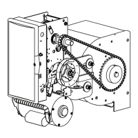
Illustrated parts breakdown for the hoist operator configuration.
Illustrated parts breakdown for the jackshaft operator configuration.
Illustrated parts breakdown for the jackshaft/hoist combo operator.
Details alternate motor options available for the operator, specifying types and part numbers.
Detailed list of parts for hoist output and clutch shafts.
Detailed list of parts for jackshaft clutch shafts.
Detailed list of parts for hoist/release combo clutch shafts.
Illustrated breakdown of parts within the operator's electric box.
Diagram showing the layout of components within the electric box for single and three phase.
List of terminals, their functions, input types, and connection types.
Table of condition codes and their corresponding descriptions for operator run status.
Continuation of error code displays and their descriptions for troubleshooting.