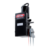
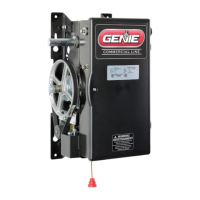
The Operator can be assembled for right or left hand
mounting above or below the door shaft and is available with or
without hoist.
If you will be using the Tension Plate Kit shown on page 4.6, slide the
bearing plates on the operator output shaft. Assembly of the kit will be
done after the drive chain is installed.
1) Install #50 sprocket on operator output shaft.
2) Align keyways and insert key into sprocket. Do not tighten set
screws at this time.
4)
Align keyways and insert key into sprocket. Do not tighten set
screws at this time.
3)
Install #50 sprocket on door shaft.
INSTALLATION TIP:
While sprocket set screws are loose, if possible, manually operate
door to help align chain. A properly tensioned drive chain should deflect
no more than 1/2” when thumb pressure is applied mid-way between the
2 sprockets. While there is no hard and fast rule governing chain tension,
it must be tight enough to prevent clicking, popping and jumping the
teeth of the sprocket. The 1/2” guideline will insure sufficient tension.
Figure
5
4.4
www.geniecompany.com 01-14
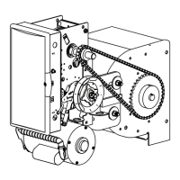
Chain Couple Installation Figure 5.
Sectional Doors
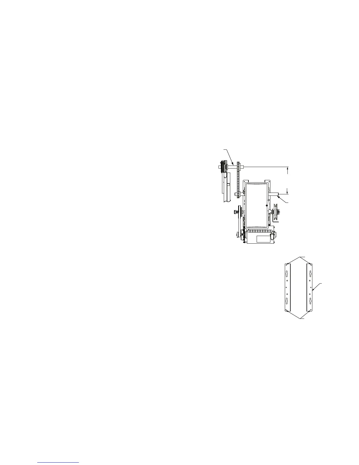
LOCK DOWN HOLES
LOCK DOWN
HOLES
OPERATOR
MOUNTING
BRACKETS
5) Assemble #50 chain using master link.
6) Align the door sprocket and operator output sprocket and
wrap #50 roller chain around both. Lock sprockets in place
by tightening their set screws.
7) Raise or lower operator to remove slack from the chain.
Ensure operator output shaft is parallel with door shaft.
8) Secure Operator to the wall using lock down holes. Lock down
holes must be used to ensure proper chain tension.
NOTE: Operator must be
securely fastened to the wall
using lock down holes to
ensure proper chain tension.
If using slotted mounting
holes to mount the unit, you
must use at least (2) lock
down holes in opposite
corners to firmly mount
the unit to the wall.
NOTE: Door shaft
and operator output
shaft must be parallel
12”-15”
CENTER
DISTANCE
OPERATOR
OUTPUT SHAFT
DOOR
SHAFT
NOTE: On Jackshafts units, release cable must be installed on operator
before unit is installed.
 Loading...