ENGLISH
22
Push-button P1 is used to select the function to be
programmed.
Push-button P2 is used to modify the value of the
selected function.
-If you press push-button P1, LED A lights up; use push-
button P2 to select the required logic as shown in table 5.
-If you press push-button P1 again, LED B lights up; use
push-button P2 to select the required pause times (for
logics A, AP and S only) as shown in table 5.
-If you press push-button P1 again, LED C lights up; use
push-button P2 to select the required partial opening
width as shown in table 5.
-If you press push-button P1 again, LED D lights up;
use push-button P2 to select the static force of the
operators as shown in table 5.
-If you press push-button P1 again, LED E lights up; use
push-button P2 to select the speed of the operators as
shown in table 5.
-If you press push-button P1 again, the five LEDs light up
steadily to indicate access to the learning function.
•Automatic learning
By using just one command, this procedure enables self-
learning of work times and decelerations. Check if the
gate is closed.
While the 5 LEDs are lighted steadily, briefly press (about
1 second) the P2 push-button - the gate starts the
opening manoeuvre, and the function LEDs begin
flashing; wait for the gate to reach the opening sensor.
The learning procedure has finished.
Press push-button P1 to exit programming.
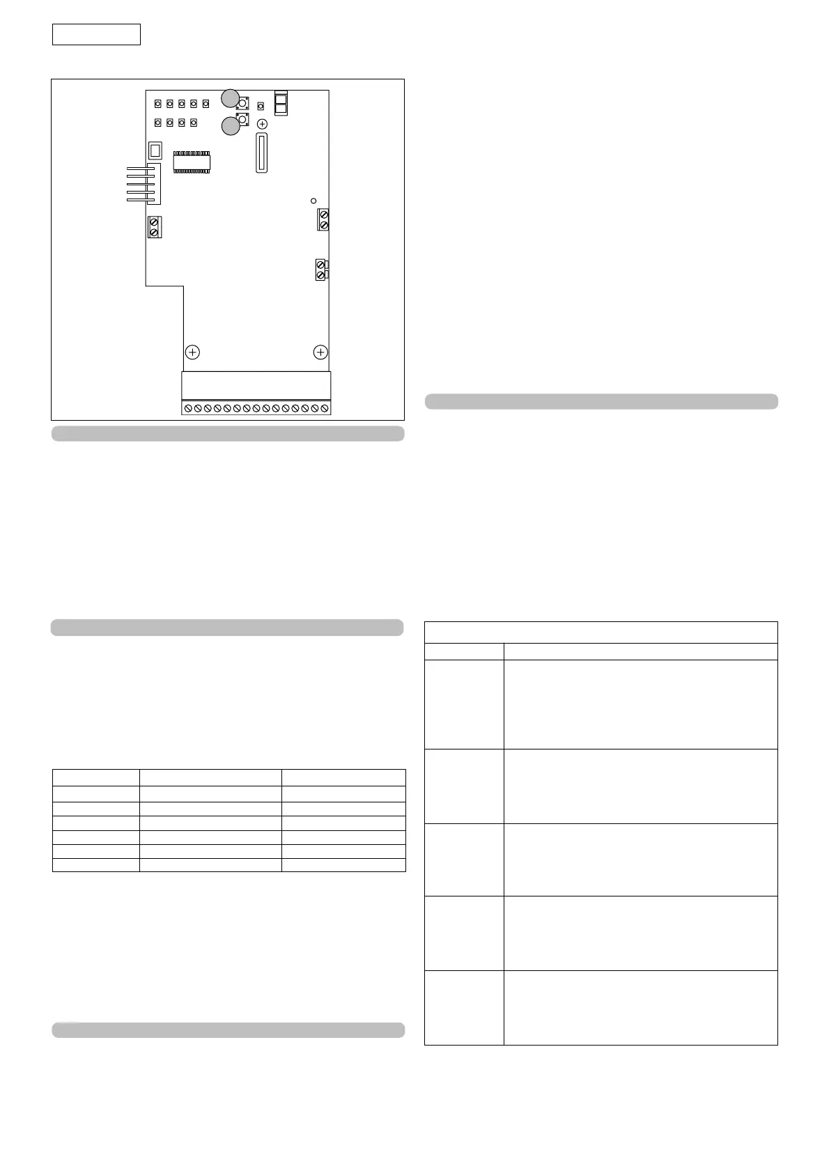
Fig. 39
11. PROGRAMMING
To access the "PROGRAMMING" mode, press push-
buttons P1 and P2 (fig. 39). The 5 programming functions
are indicated by LEDs with letters, whereas the modifiable
values are indicated by numbered LEDs.
9. Diagnostics
The "P" LED (see fig.21) has a diagnostics function. The LED
has 4 statuses:
•Steady light: mains power ON and battery charged.
• Slow flashing (lights every second) : no mains power but
battery charged.
•Rapid flashing (lights every 250 msec): power ON but
battery discharged.
•Light OFF: no mains power supplied and battery
discharged
10. Inputs status
The equipment has a function for checking the status of
the terminal board inputs.
How to access this function:
In the "all LEDs off status" (both lettered and numbered),
press push-button P2; the statuses of the inputs as shown
in table 4, will be shown in the lettered and
numberedLEDs columns.
Led ON OFF
A = Open A Command active Command inactive
B = Open B Command active Command inactive
C = Stop Command inactive Command active
D = Fsw op
Safety devices disengaged
Safety devices engaged
E = Fsw cl
Safety devices disengaged
Safety devices engaged
1 = Sensor Sensor disengaged Sensor engaged
N.B.: The LED status check function remains active for 5
minutes after which the board returns to the "All LEDs OFF"
status.
IMPORTANT: When the inputs status function is accessed, the
accessories are all powered even if the gate is idle. The P1
push-button is active and can be used as Open A.
Table 4
Programming
Table 5
Function LED Function
A Function logic
(see tables 6/a, 6/b, 6/c and 6/d)
1 = A (automatic)
2 = S (safety)
3 = AP (stepped automatic)
4 = EP (stepped semi-automatic)
B Pause times
1 = 5 seconds
2 = 10 seconds
3 = 20 seconds
4 = 30 seconds
C Partial opening width
1 = 90 cm.
2 = 120 cm.
3 = 150 cm.
4 = 180 cm.
D Static force
1 = low
2 = medium low
3 = medium high
4 = high
E Speed
1 = low
2 = medium low
3 = medium high
4 = high
At the end of the checks, press push-button P2 again to
exit the inputs status function.
N.B.:The equipment remains in programming status for 5
minutes; if no push-button is pressed after this time
elapses, the board returns to the all LEDs OFF status.
2
ED
C
B
1
A
3
4
J10
J4
F1
J3
J2
J1
P1
P2
 Loading...