ENGLISH
17
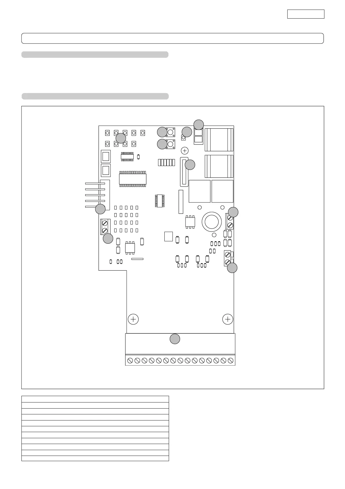
Fig. 21
5. WARNINGS
Important: Before attempting any job on the control board (connections, maintenance), cut out power supply and the battery.
- Install, upstream of the system, a differential thermal breaker with adequate tripping threshold.
- Always separate 230VAC power cable from control and safety cables (push-buttons receiver, photocells, etc.). To avoid any
electrical noise, use separate sheaths or a shielded cable (with earthed shield).
6. LAY-OUT OF CONTROL BOARD COMPONENTS
LED Programming LEDs
P Power ON and diagnostics LED
P1 "Function" programming push-button
P2 "Value" programming push-button
F1 Battery and motor fuse - F20A
J1 Accessories Terminal board
J2 Transformer Terminal board
J3 Motor connection Terminal board
J4 Battery connector
J5 Minidec connector/RP Receiver
J10 Sensor Terminal board
CONTROL BOARD
LED
P
P1
P2
F1
J1
J2
J3
J4
J5
J10