ENGLISH
16
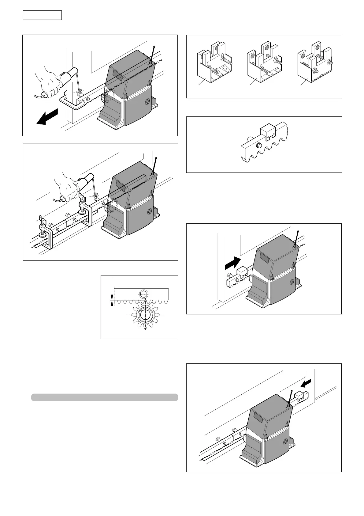
Fig. 15
• Make sure that, during the
gate travel, all the rack
elements mesh correctly
with the pinion.
• Do not, on any account,
weld the rack elements
either to the spacers or to
each other.
• When you have finished
installing the rack, adjust
the distance between the
Notes on rack installation
pinion teeth and the rack groove, checking if the distance
is 1.5 mm (Fig. 16) along the entire travel, using the rack slots.
• Manually check if the gate habitually reaches the travel limit
mechanical stops and make sure that there is no friction
during gate travel.
• Do not use grease or other lubricants between rack and
pinion.
Fig. 16
4.5. POSITION THE TRAVEL LIMIT MAGNETS
The Step operator is supplied with a sensor which, by
detecting the transit of two magnets secured to the top of
the rack, commands gate movement to stop. Procedure for
correct positioning of the two supplied magnets:
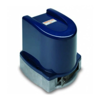
• Assemble the magnets according to the type of rack used,
as shown in points 1,2 and 3 below.
1) Galvanised rack 30x6 module 4 (Fig. 17 ref. 햲)
2) Galvanised rack 30x12 module 4 (Fig. 17 ref. 햳)
3) Reinforced nylon rack 30x20 module 4 (Fig. 17 ref. 햴)
Fig. 17
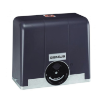
• Position the magnets on the rack as shown in figure 18.
Fig. 18
Fig. 14
• Power up the control board and enter the inputs status
function (chpt.10)
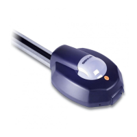
• Manually take the gate to opening position, but allow a
space of 2 cm from the travel limit mechanical stop position.
• Slide the magnet on the rack (Fig. 19) until you see that LED1
on the control board goes off.
Tighten the magnet's securing screws.
Fig. 19
• Manually take the gate to closing position, but allow a
space of 2 cm from the travel limit mechanical stop position.
• Slide the magnet on the rack (Fig. 20) until you see that LED1
on the control board goes off.
Tighten the magnet's securing screws.
• Re-lock the operator.
Fig. 20
1,5
햲
햳햴