ENGLISH
15
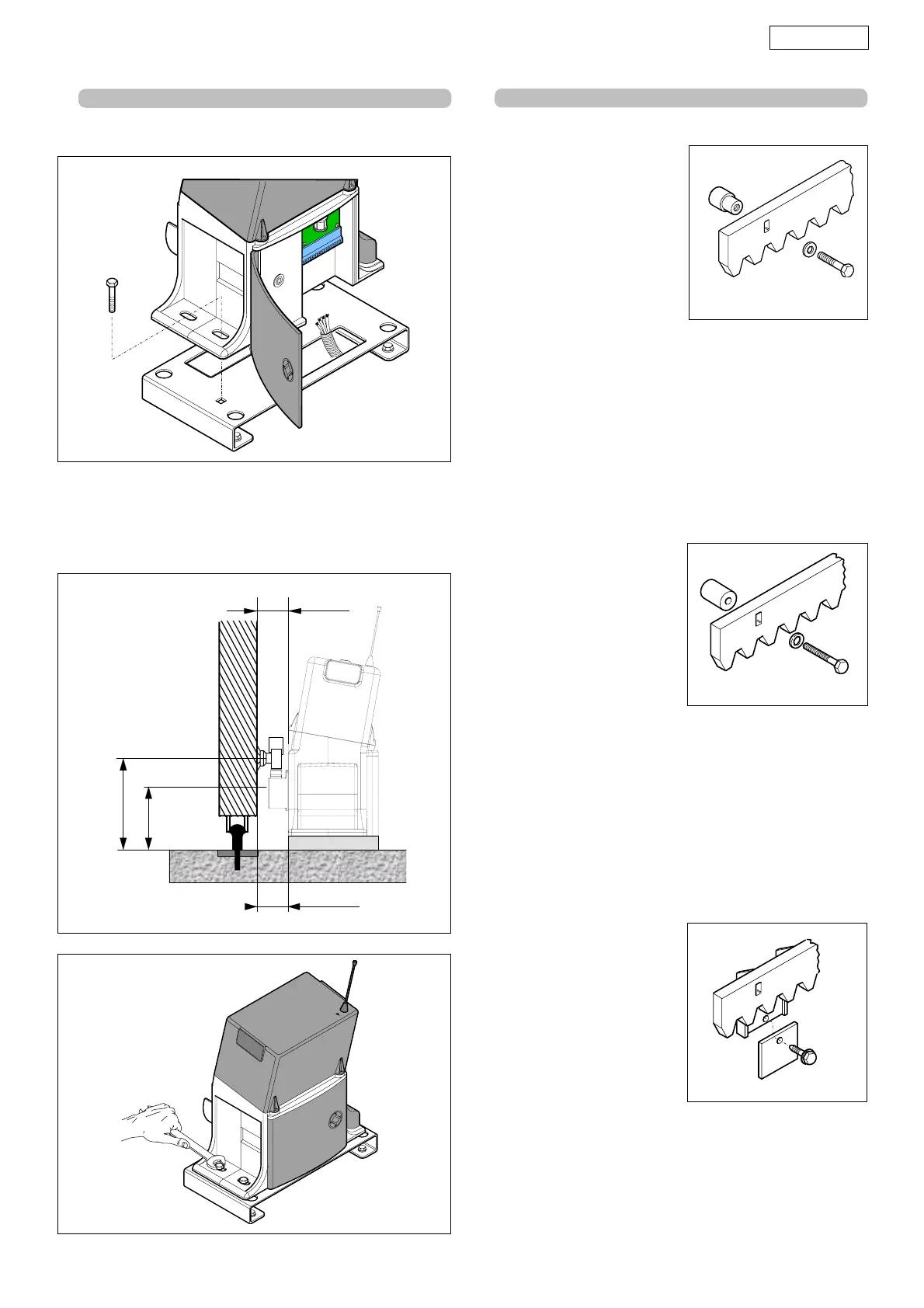
• Position the operator on the plate, using the supplied screws
as shown in figure 8.
Fig. 8
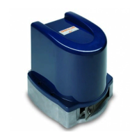
Fig. 9
4.3. MECHANICAL INSTALLATION
• Adjust the distance of the operator from the gate by referring
to fig. 9.
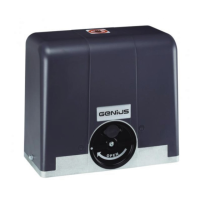
• Secure the gearmotor to the foundation plate, tightening
the screws as in Fig.10.
• Prepare the operator for manual operating mode as
described in chapter 13.
4) Move the gate manually, checking if the rack is resting on the
pinion, and weld the second and third pawl.
5) Bring another rack element near to the previous one, using
a piece of rack (as shown in figure 15) to synchronise the teeth
of the two elements.
6) Move the gate manually and weld the three threaded
pawls, so proceeding until the gate is fully covered.
Fig. 12
4.4.2. STEEL RACK TO BE SCREWED (Fig.12)
1) Manually take the leaf into
its closing position.
2) Lay the first piece of rack at
the appropriate level on the
pinion and place the spacer
between rack and gate,
positioning it at the top of
the slot.
3) Mark the hole position on
the gate. Drill a Ø 6.5 mm
hole and thread with a Ø 8
mm tap.
Screw the bolt.
4) Move the gate manually,
checking if the rack is resting on the pinion, and repeat the
operations at point 3.
5) Bring another rack element near to the previous one, using
a piece of rack (as shown in figure 15) to synchronise the teeth
of the two elements.
6) Move the gate manually and carry out the securing
operations as for the first element, proceeding until the gate
is fully covered.
4.4.3. NYLON RACK TO BE SCREWED (Fig.13)
Fig. 13
a piece of rack (as shown in figure 15) to synchronise the
teeth of the two elements.
5) Move the gate manually and carry out the securing
operations as for the first element, proceeding until the
gate is fully covered.
1) Manually take the leaf into its
closing position.
2) Lay on the pinion the first piece
of rack at the appropriate
level and mark the hole
position on the gate; make a
hole with a 4 mm bit and
screw the 6x20 mm self-
tapping screw with reinforcing
plate.
3) Move the gate manually,
checking if the rack is resting
on the pinion, and repeat
the operations at point 2.
4) Bring another rack element
near to the previous one, using
Fig. 10
Fig. 11
4.4. INSTALLING THE RACK
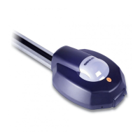
4.4.1. STEEL RACK TO BE WELDED (Fig. 11)
1) Place the three threaded
pawls on the rack element,
positioning them at the top
of the slot. In this way, the slot
play will enable any
adjustments to be made.
2) Manually take the leaf into
its closing position.
3) Lay the first piece of rack at
appropriate level on the
pinion and weld the
threaded pawl on the gate
as shown in figure 14.
46,5÷51,5
112,5÷146
106
36,5÷41,5