ENGLISH
14
햲햲
햲햲
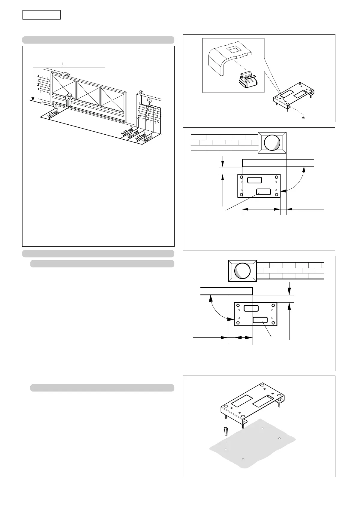
햲 Step operator with equipment.
햳햳
햳햳
햳 Photocells
햴햴
햴햴
햴 Key operated push-button
햵햵
햵햵
햵 Flashing lamp
햶햶
햶햶
햶 Radio receiver
Fig. 3
Notes: 1)To lay electric cables, use adequate rigid and/or
flexible tubes.
2)Always separate low voltage connection cables from
those operating at 230 Vac. To prevent any
interference whatever, use separate sheaths.
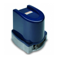
4.2. SECURING THE FOUNDATION PLATE
• Fit the 4 supplied caged nuts, as shown in figure 4, in the 4
square holes of the plate.
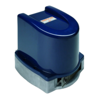
• The foundation plate must be located as shown in figure 5
(right closing) or figure 6 (left closing) to ensure the rack and
pinion mesh correctly.
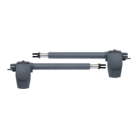
• Secure the foundation plate to the floor, using adequate
expansion plugs (fig. 7) and provide one or more sheaths for
routing the electric cables. Using a spirit level, check if the
plate is perfectly level.
• Lay the electric cables for connection to the accessories and
power supply as shown in figure 3.
To facilitate making the connections, allow the cables to
project by about 20 cm from the hole (Fig.5-6 ref. 햲) of the
foundation plate.
4. INSTALLING THE AUTOMATED SYSTEM
4.1. PRELIMINARY CHECKS
To ensure safety and an efficiently operating automated system,
make sure the following conditions are observed:
• The structure of the gate must be suitable for it to be
automated. In particular, wheel diameter must be in relation
to the weight of the gate to be automated, and dimensions
and weight must match those indicated in the technical
specifications.
• Make sure that the gate slides without any inclination.
• Make sure that the gate moves uniformly and correctly,
without any irregular friction during its entire travel.
• The soil must permit sufficient stability for the expansion plugs
securing the foundation plate.
• Check if the upper guide and travel limit mechanical stops
are installed.
We advise you to have any metalwork carried out before the
automated system is installed.
3. ELECTRONIC EQUIPMENT (standard system)
Fig. 6
• Dimensions in mm
*Use the dimensions according to type of rack.
Galvanised rack 30x6 = 36.5
Galvanised rack 30x12 = 39.5
Nylon rack 30x20 = 41.5
Fig. 5
Fig. 7
Fig. 4
햲
햲
*
*
• Dimensions in mm
*Use the dimensions according to type of rack.
Galvanised rack 30x6 = 36.5
Galvanised rack 30x12 = 39.5
Nylon rack 30x20 = 41.5
36,5
÷
41,5
175,5
0
÷
50
90
°
36,5
÷
41,5
0
÷
50
90,5
90
°
2x1,5 mm + (230Vac)
2