ENGLISH
21
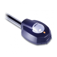
8.4. J3 Terminal board - Motor Connection
This terminal board is used for connecting the motor (see fig.
22) . For the colour of the wires, refer to fig.32 (right closing) and
to fig. 33 (left closing).
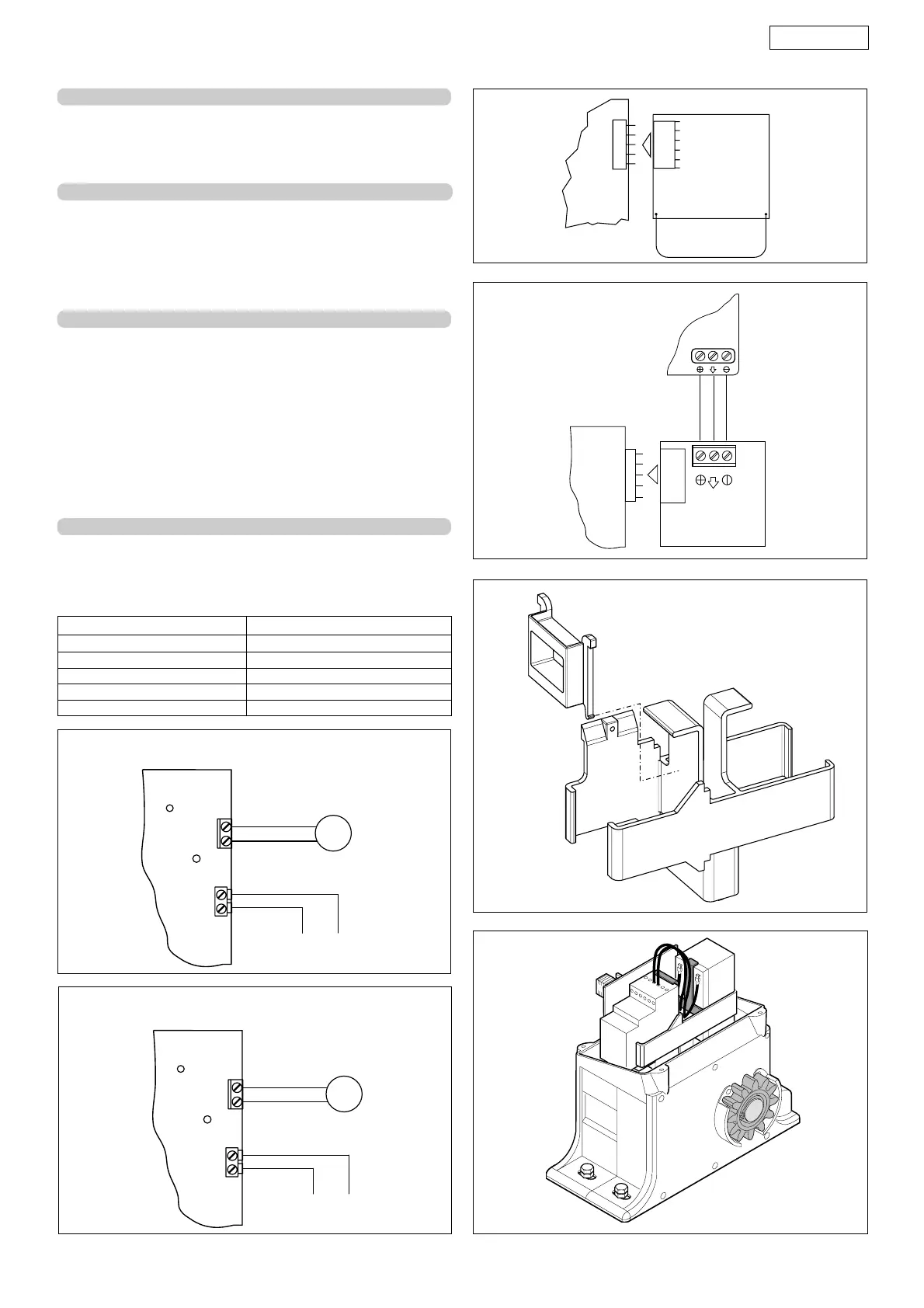
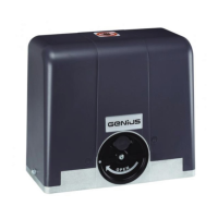
8.5. J4 Connector - Battery connection
Connect the operator battery (Fig. 22) to this connector.
The battery is housed as shown in figure 37.
N.B.: The batteries are not supplied fully charged; however,
the charge is sufficient for programming and setting-up the
system.
8.6. J5 Connector - Quick-fit for Minidec and Rp - 12 Vdc
This is used for rapid connection of the Minidec cards and RP
receivers.
IMPORTANT: do not use Decoder cards on the quick-fit
connection.
In case of a mains power cut, this connector is powered for
twelve hours - after this time, the opening push-buttons
(terminals 1 and 2) are the only active commands.
The connector is powered down to store sufficient energy for
running some emergency manoeuvres in the space of 30
days.
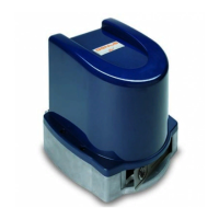
8.7. J10 Terminal board - Connection of travel limit sensor
It is used for connecting the travel limit detection sensor.
Tab. 3
Gate status Indicator-light status
Closed Light Off
Open - Open in pause Lighted
Closing Flashing
Opening Lighted
Blocked Lighted
Fig. 35
Fig. 34
BROWN
BLUE
Fig. 32
Fig. 33
BLUE
BROWN
Right closing
Left closing
Fig. 36
Fig. 37
M
12 Vac
J2
J3
M
12 Vac
J2
J3
MINIDEC
PLUS
RP