ENGLISH
20
8.2. J1 TERMINAL BOARD - ACCESSORIES (FIG. 22)
Low voltage terminal board used for connecting all
accessories.
24 Vdc
– Negative for powering accessories (terminals 12,13,14,15)
+ Positive for powering accessories + 24 Vdc (terminals 7
and 8)
Important: The maximum load of the accessories powered
at 24 Vdc is 150 mA. When the automated system is idle, the
accessories are not powered. To calculate absorption values,
refer to the instructions for individual accessories.
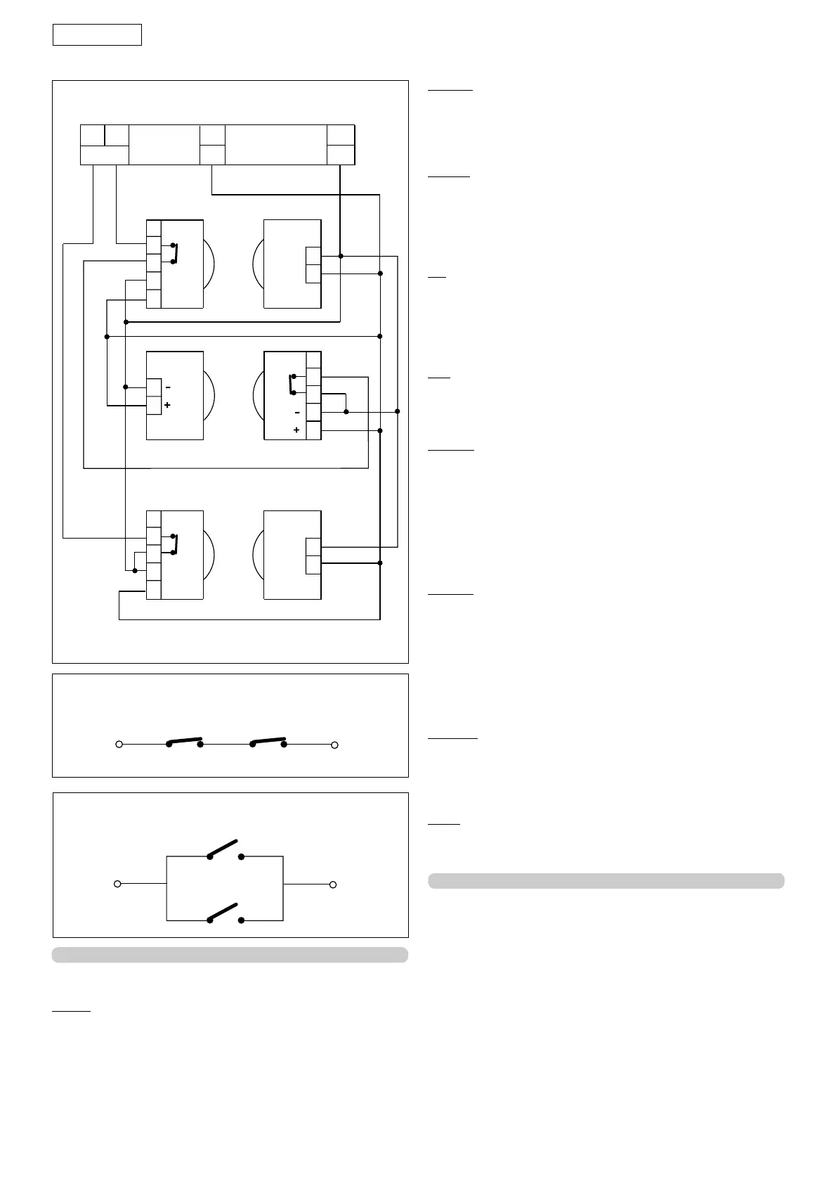
Fig. 29
Connection of 2 pairs of closing photocells and 1 pair of
opening photocells.
OPEN A - "TOTAL OPENING" (terminal 1) OPEN command: any
device (e.g.: push-button) which, by closing a contact,
supplies an opening or closing pulse to the gate.
To install several opening pulse generators, connect the N.O.
contacts in parallel (see fig.31).
OPEN B -"PARTIAL OPENING" (terminal 2) OPEN command: any
device (e.g.: push-button) which, by closing a contact,
supplies a pulse for partial opening and/or closing of the
gate.
To install several opening pulse generators, connect the N.O.
contacts in parallel ( fig.31).
STP - STOP Command (terminal 3): any device (e.g.: push-button)
which, by opening a contact, stops gate movement.
To install several stop devices, connect the N.C. contacts in
series (fig. 30).
NB.: If STOP devices are not connected, jumper connect the
inputs STP and -.
FSW
All devices (photocells, sensitive edges, magnetic loops) with
N.C. (normally closed) contact, which, if there is an obstacle
in the area they protect, operate to interrupt gate movement.
FSW OP. - Opening safety devices contact (terminal 4): during
opening, the safety devices reverse motion to closing. They
do not operate during closing.
If the Opening safety devices are tripped when the gate is
closed, they prevent the gate opening movement.
NB.: If no opening safety devices are connected, jumper
connect inputs OP and - (fig. 23).
The opening safety devices protect the area behind the
gate.
FSW CL. - Closing safety devices contact (terminal 5): during
closing, the safety devices reverse motion to opening. They
do not operate during opening .
If the Closing safety devices are tripped when the gate is
open, they prevent the closing movement.
NB.: If no closing safety devices are connected, jumper
connect inputs CL and - (fig. 23).
The closing safety devices protect the area affected by the
movement of the gate as it closes.
W. LIGHT - (terminals 9 and 11): Power supply for the indicator-
light, 12 Vdc 0.5 W max. (terminals 9 and 11). To avoid
compromising correct operation of the system, do not exceed
the indicated power. For instructions on operation of the
indicator- light, consult table 3.
LAMP - (terminals 10 and 11): Flashing lamp output, 12 Vdc 21 W.
BA15S lamp. To avoid compromising correct operation of the
system, do not exceed the indicated power.
8.3. J2 Terminal board
It is used for connecting the transformer (optional), 12 Vac 16
VA. Fit the transformer support as shown in figure 36. Place the
transformer in its compartment, as shown in figure 37, and
make the connection as shown in figure 22. Alternatively, the
transformer can be remotely located up to a distance of 100
mt from the equipment, using wires with a diameter of 0.5
mm
2.
Connection of 2 N.C. contacts in series
(E.g. Photocells, Stop)
Fig. 30
Connection of 2 N.O. contacts in parallel
(E.g. Open A, Open B)
Fig. 31
TX OPRX OP
RX CL
TX CL
TX CLRX CL
1
2
5
4
3
1
2
1
2
5
4
3
1
2
-
+
-
+
1
2
5
4
3
1
2
-
+
-
+
FSW
—
4 5
12
7
+