EasyManuals Logo

GeoVision GV-AS2120 User Manual

GeoVision GV-AS2120
235 pages
To Next Page IconTo Next Page
To Previous Page IconTo Previous Page
Page #216 background imageLoading...
Page #216 background image
198
9.3.2.C Status Monitor
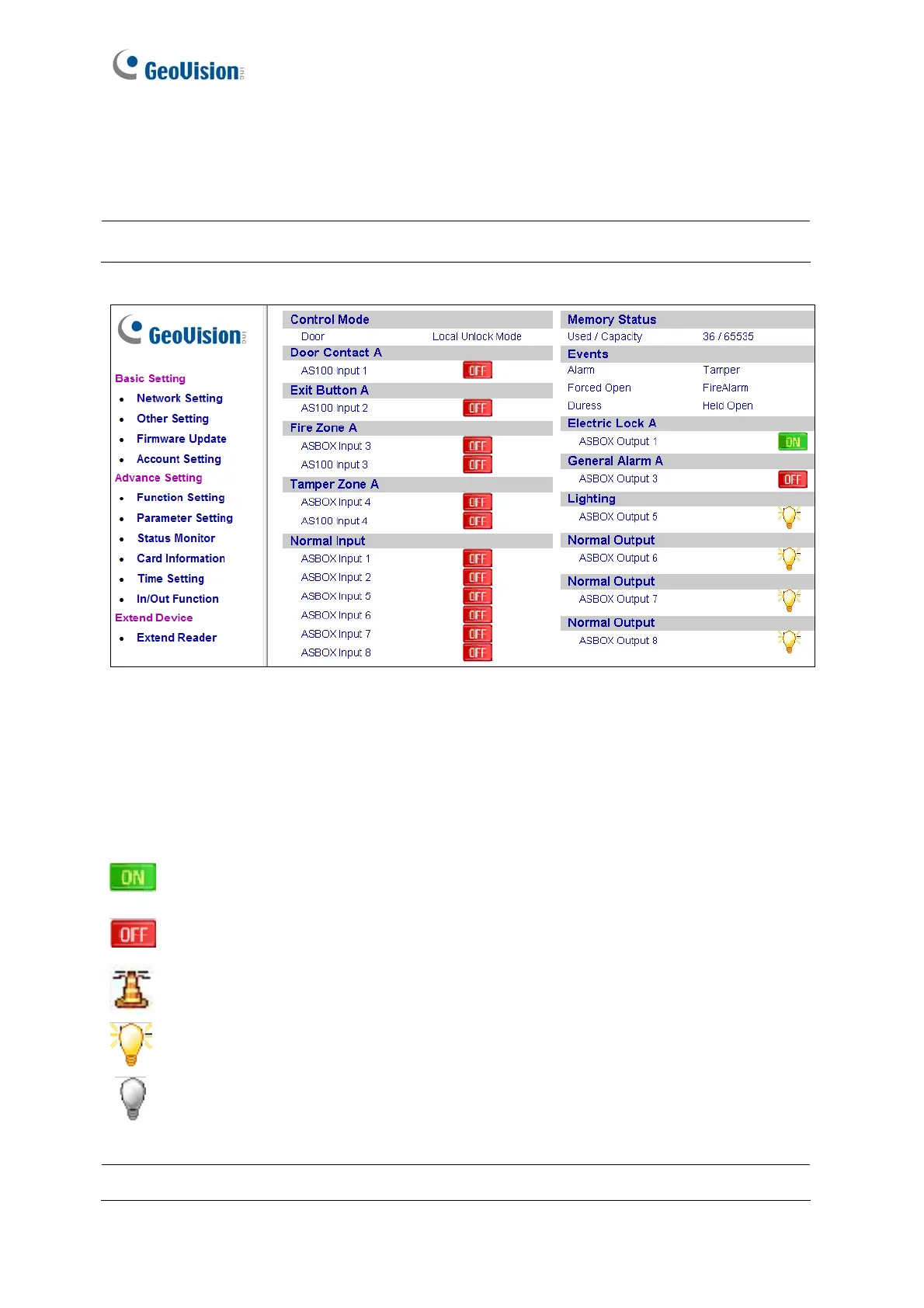
In the left menu, click Status Monitor to see the status of each input, output and alarm
Figure 9-20
Control Mode will change depending on the chosen Door/Gate’s Authentication Mode in
the Function Setting page (Figure 9-15). The listed number of outputs will change
depending on the chosen Output Type in the In/Out Function page (Figure 9-23).
= Indicates the current input/output device is triggered.
= Indicates the current input/output source is not triggered.
= Indicates the current event is triggered.
= Indicates the current light is on.
= Indicates the current light is off.
Note: The Status Monitor page is only available when connecting through a GV-ASBox.
Note: Outputs must be turned on in the In/Out Function page to be monitored here.

Table of Contents

Other manuals for GeoVision GV-AS2120

Questions and Answers:

Question and Answer IconNeed help?

Do you have a question about the GeoVision GV-AS2120 and is the answer not in the manual?

GeoVision GV-AS2120 Specifications

General IconGeneral
TypeIntelligent access control reader
CertificationCE, FCC
Number of users100000 user(s)
Access code reader-
Fingerprint readerYes
Authentication typeAccess chip/card
Sustainability certificatesRoHS
Operating temperature (T-T)0 - 65 °C
Operating relative humidity (H-H)10 - 90 %
DC current (max)3 A
DC voltage range12 - 30 V
Power consumption200 mA
RS-485 ports1
Weight and Dimensions IconWeight and Dimensions
Depth46.6 mm
Width210 mm
Height204 mm
Weight810 g

Related product manuals