Introduction
3
1
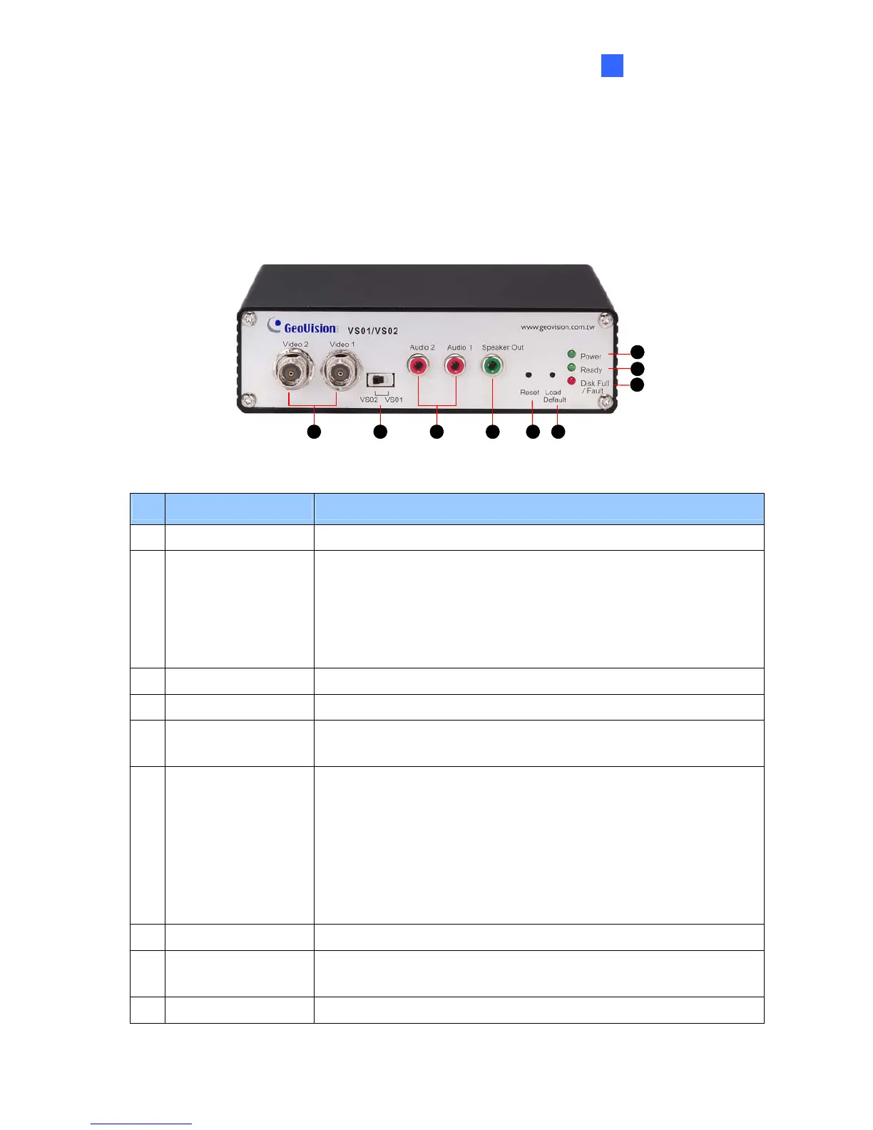
1.5 Physical Description
This section identifies the various components of the GV-Video Server.
1.5.1 Front View
3 6
7
8
9
2 4 51
Figure 1-1
No. Name Function
1 Video Input 2 plugs for video inputs.
2 Video Stream Switch
The switch is designed for 2 cameras mode in live view.
When the switch is set in
VS01, dual streams of Video 1 are displayed.
VS02, Video 1 and Video 2 are displayed simultaneously.
Ensure to reboot the GV-Video Server after changing the setup.
3 Audio Input 2 plugs for audio inputs.
4 Speaker Output A plug for the speaker device.
5 Reset Button
It reboots the GV-Video Server, and keeps all current
configurations.
6 Default Button
It resets all configurations to their factory settings.
To use this function, follow these steps:
1. Press and then release the Reset button.
2. Press and hold the Default button until the 3 LED lights are on.
3. Release the Default button. Wait until the Disk LED is off and
Ready LED is on. You successfully return to the default
settings.
7 Disk Full/Fault LED This LED is on, indicating the hard drive is full or faulty.
8 Ready LED
This LED is on, indicating the GV-Video Server is ready for
connection.
9 Power LED This LED is on, indicating the power is supplied.
 Loading...