11
LRR 1-50, LRR 1-51 - USA - Installation & Operating Manual - 850702-01
LRR 1-50, LRR 1-51
Supply voltage
24 VDC +/– 20%; PELV / CLASS2
Fuse
External M0.5A (medium time-lag)
Power consumption
4 W
Reset hysteresis
MAX limit: –3% of set MAX limit, factory default.
Outputs
2 volt-free relay contacts, 8A 250V AC / 30V DC cos ϕ = 1
(continuous blowdown valve OPEN, OPERATING, CLOSED).
1 volt-free relay contact, 8A 250V AC / 30V DC cos ϕ = 1
(MAX alarm, switch-selectable).
Inductive loads must have interference suppression (RC combination) as specified by the
manufacturer.
1 analog output 4-20mA, max. output load 500ohms, e.g., for an actual value display.
Indicators and controls
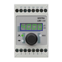
1 rotary knob with integrated push-button for testing the MAX alarm and setting the parameters,
1 4-digit 7-segment LED display,
1 red LED for MAX alarm,
2 yellow LEDs for continuous blowdown valve opening/closing
1 4-pole code switch for configuration.
Terminal box
Terminal box material: base of black polycarbonate, front of gray polycarbonate
Wire size: 1 x AWG12 (4.0 mm
2
) solid, or
1 x AWG14 (2.5 mm
2
) stranded with sleeve acc. to DIN 46228, or
2 x AWG16 (1.5 mm
2
) stranded with sleeve acc. to DIN 46228
Terminal strips can be removed separately
Terminal box attachment: Mounting clip on support rail TH 35, EN 60715
Electrical safety
Pollution degree 2, overvoltage category II according to UL 60730-1
Protection
Terminal box: IP40 according to EN 60529
Terminal strip: IP20 according to EN 60529
As a UL open type, the equipment must be installed in a control cabinet.
Weight
Approx. 0.44 lb (0.2 kg)
Other information
Incorporated type 1 action operating control
Pollution degree 2, impulse voltage DC supply = 500 V, AC output = 2500 V
Technical data

 Loading...