32
LRR 1-50, LRR 1-51 - USA - Installation & Operating Manual - 850702-01
Attention
Please check the following before fault diagnosis:
Supply voltage:
Is the conductivity controller supplied with the voltage specified on the rating plate?
Wiring
Does the wiring conform to the wiring diagram?
Fault indications and troubleshooting
Indications, diagnosis and corrective action
Attention
■ For further troubleshooting, please refer to the LRG 16-4, LRG 16-9 and LRGT
1.-.. Installation & Operating Manuals.
Note
In the event of a fault in the conductivity controller, the MAX alarm is triggered and
the equipment restarts. If the process repeats itself continuously, the equipment
must be replaced.
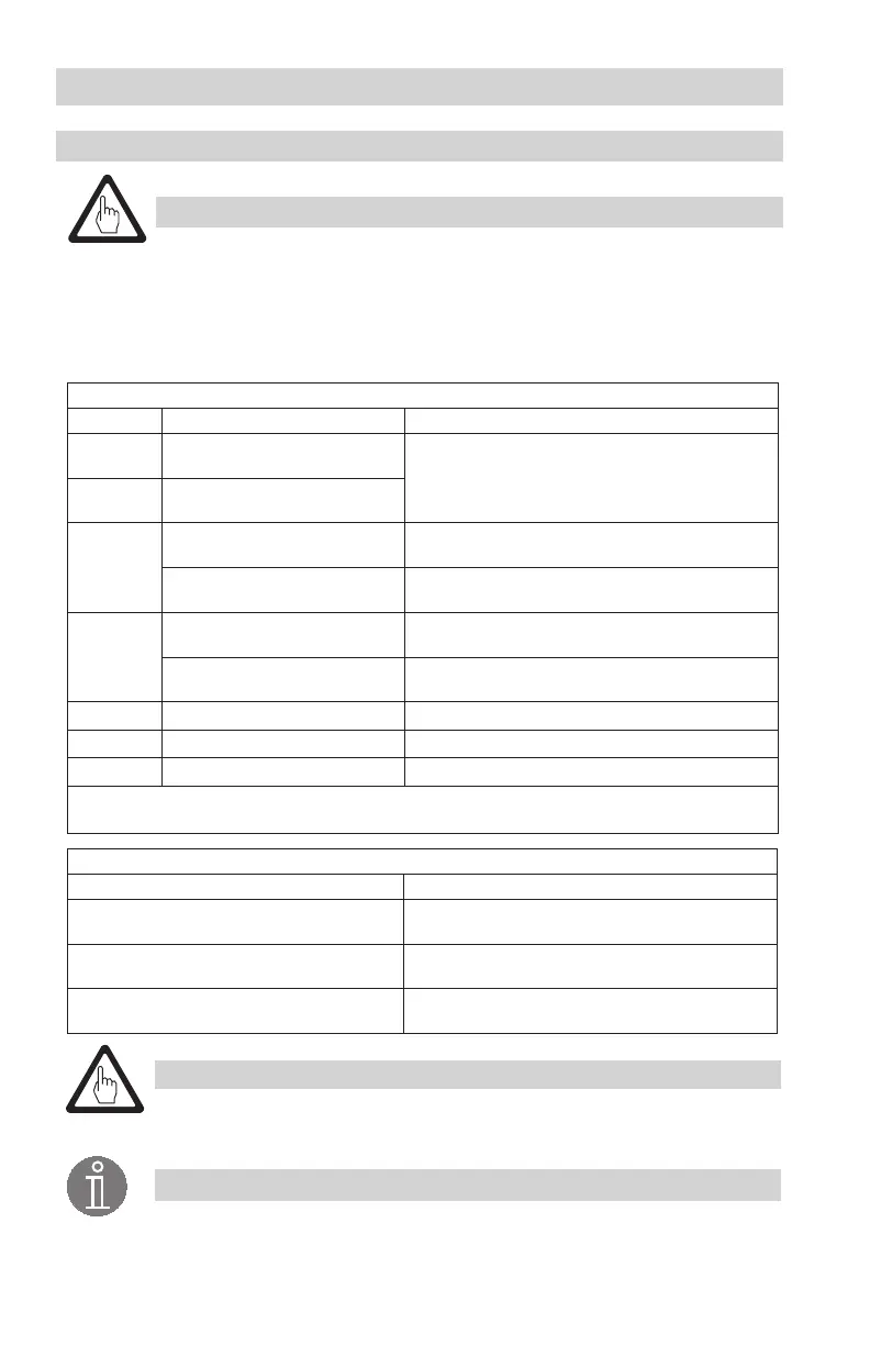
Error codes on the 7-segment display
Error code Error Corrective action
E.001
Faulty temperature sensor,
temperature reading too low
Check resistance thermometer and LRG 16-9 conduc-
tivity electrode and replace if necessary. Check electri-
cal connection (short circuit, open circuit?).
E.002
Faulty temperature sensor,
temperature reading too high
E.005
Faulty conductivity electrode,
reading too low.
Check conductivity electrode and replace if necessary.
Check electrical connection.
Faulty conductivity transmitter,
measuring current < 4mA
Check conductivity transmitter and replace if neces-
sary. Check electrical connection.
E.006
Faulty conductivity electrode,
reading too high.
Check conductivity electrode and replace if necessary.
Check electrical connection. Check boiler water.
Faulty conductivity transmitter,
measuring current > 20mA
Check conductivity transmitter and replace if neces-
sary. Check electrical connection.
E.097 Walkthrough application error Internal error. Replace equipment.
E.098 Walkthrough test error Internal error. Replace equipment.
E.099 Internal test error Internal error. Replace equipment.
In the event of a fault, the MAX alarm is triggered and the continuous blowdown valve moves into
OPERATING position.
Errors without an error code
Error Corrective action
Actual value < set point. Continuous blowdown
valve opens.
Check code switch S4. Switch must be in the ON
position.
4-20 mA actual value display remains in the 4-8
mA or 20 mA range when the conductivity changes
Check code switch S3 with the help of the table
on p. 19. Switch must be in the OFF position
4-20 mA manipulated variable output (Yw)
changes proportional to conductivity.
Check code switch S3 with the help of the table
on p. 19. Switch must be in the ON position

 Loading...


