18
LRR 1-50, LRR 1-51 - USA - Installation & Operating Manual - 850702-01
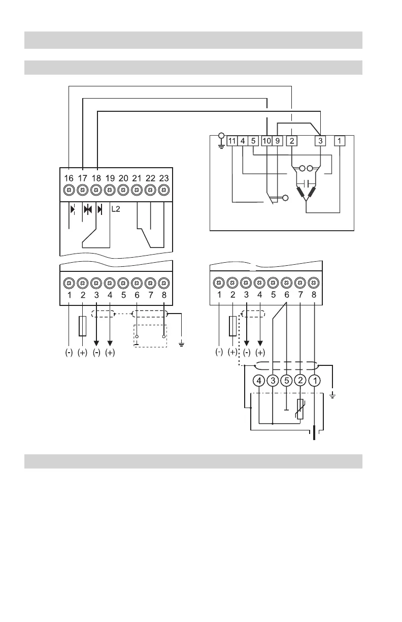
In the control cabinet: Electrically connecting the conductivity controller
Wiring diagram of the LRR 1-50 conductivity controller
5 Connection of supply voltage 24V DC
with 0.5A medium time-lag fuse provided by
customer
6 Actual value/manipulated variable output 4-20 mA
(switch-selectable)
7 Conductivity electrode LRG 16-4 (terminal 6/7:
a resistance thermometer can be connected)
8 Central grounding point (CGP) in control cabinet
Key
9 Conductivity electrode LRG 16-9
with integrated resistance
thermometer
0 MAX output contact
a Supply voltage L2
b Supply voltage N
OPERATING
OPEN
CLOSED
Actuator EF
M0.5A
(medium
time-lag)
M0.5A
(medium
time-lag)
5
8
b
7
6
8
9
5
a
0
When the burner, and therefore the supply
voltage to the controller, is switched off (stand-
by), L2 must remain on until the actuator has
closed the continuous blowdown valve.
Fig. 3
6

 Loading...


