25
LRR 1-50, LRR 1-51 - USA - Installation & Operating Manual - 850702-01
Operating the conductivity controller
Meaning of codes on the 7-segment display
Code Meaning
Indicated when rotary knob is turned clockwise:
AL.Hi Alarm High MAX switchpoint, adjustable from 0.5 to 4999.5ppm (1 to 9999µS/cm)
SP Set point Adjustable from 0.5 to 4999.5ppm (1 to 9999µS/cm)
HySt Hysteresis Reset hysteresis, adjustable from 1 to 25% of set point
FiLt Filter Switching the filter on/off (damping)
PW
Password on = password protection is enabled oFF = password protection is disabled
Factory default setting
1902 (cannot be changed)
Indicated in parameterization mode
quit Quit Entry is not confirmed
done Done Entry is confirmed
Indicated in the event of errors
E.001 Error Faulty temperature sensor, temperature reading too low (LRR 1-50 only)
E.002 Error Faulty temperature sensor, temperature reading too high (LRR 1-50 only)
E.005 Error Faulty measured value acquisition, reading too low
E.006 Error Faulty measured value acquisition, reading too high
LRR 1-50 only
CAL
Electrode
calibration
Electrode calibration, last reading
is shown
CF
Correction
factor
Adjustable from 0.05
to 5.000 in increments
of 0.001
inP
Input for
Pt100
Temperature compensation
YES (no)
tC
Temperature
coefficient
tC 0.0 – 3.0% per °C,
adjustable in increments of 0.1
LRR 1-51 only
Sin.L
Lower end of measuring range, adjustable
from 0.0 - 0.25 - 25 - 50 ppm
(0 - 0.5 - 50 - 100 µS/cm)
Sin.H
Upper end of measuring range, adjustable
from 10 - 50 -
100 - 250 - 500 - 1000 -
1500 - 2500 - 3000 - 3500 - 5000 - 6000
ppm (20 - 100 - 200 - 500 -1000 -
2000 - 3000 - 5000 - 6000 - 7000 -
10000 - 12000μS/cm)
Sout
Standardization of current output, adjustable between 5 and 5000ppm
(10 and 9999µS/cm)
Si Flushing interval, adjustable from 0 to 24 hours in increments of 1h
Sd Flushing time, adjustable from 1 to 4 minutes in increments of 1min.
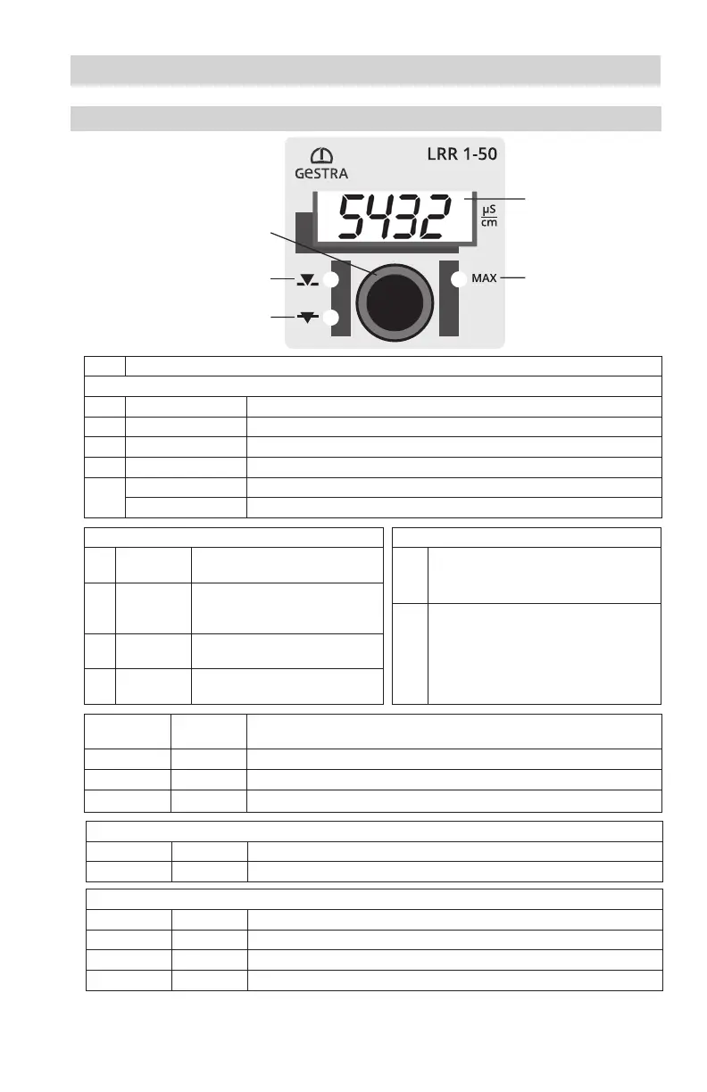
tESt Test Test of output relays
Fig. 6
Rotary knob with
integrated
push-button
Red MAX LED
7-segment display
LED 1 for
valve opening
LED 2 for
valve closing

 Loading...


