Model 9128
Marking on drawing Quantity Length (mm) Installed/Not installed
K 205/106 1 Not installed
K 206/210 2 2000 Not installed
K105 1 440 Not installed
K 208/213/108/110/209 5 1000 All installed except K 209
K 204 1 750 Installed
K 203 1 590 Installed
K 103 1 690 Installed
K 107/109/207/212 4 1000 Not installed
K 102 1 400 Not installed
K 104 1 650 Not installed
K 202/211 2 600 K 202 Installed, K211 Not
installed
K 101/201 2 1000 Not installed
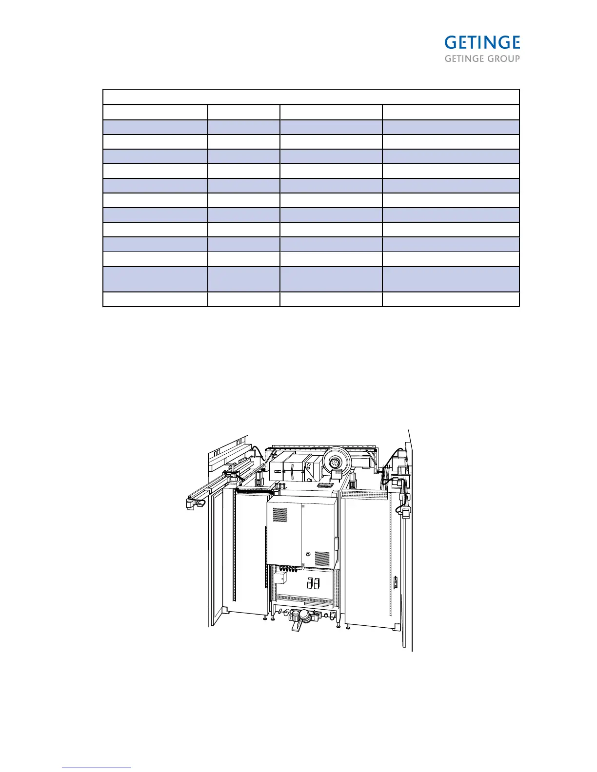
• The electrical cables are connected and coiled at the various loads. Draw the cables in the
cable ducts as shown in the illustrations below and connect them in the electrical cabinet.
• The cables for 230/400 V must be placed in the cable duct/tray with the number K1xx (cable
ducts for 24 V cables have number K2xx) as shown in the illustration on the previous page. All
cables for 230/400 V must be connected to the electrical cabinet via cable duct K102 at the
cabinet entrance on the left side. If the object is on the right side of the electrical cabinet, the
cables must be drawn over the machine in the cable tray marked K106 above the chamber.
Place remaining cable in the cable tray on top of the machine marked K106.
 Loading...