Do you have a question about the Gewiss RESTART RD and is the answer not in the manual?
Connect device power between phase and neutral cables.
Ensure system isolation before performing any intervention.
Indicates the device is powered and operational.
Shows the device is in the process of restarting.
Device is switched off and ready for a reset attempt.
Guide for manually testing the RD/RD PRO devices.
Guide for manually testing the RM/RM PRO devices.
Recommendations for test frequency and technician contact.
Procedure for automatic reset testing on RD/RD PRO models.
Procedure for automatic reset testing on RM/RM PRO models.
Performing the reset test upon initial system setup.
Steps to diagnose and identify earth faults in the system.
Meaning of the blinking red LED during installation check.
Conditions that can lead to unexpected device tripping.
How a successful reset operation is indicated.
Indicates low insulation; device enters standby mode.
Signals system fault, short circuit, or multiple trips.
Notes that green LED is only for PRO versions.
Red LED blinking indicates installation check within 90s.
Fixed red LED indicates a blocked system status.
On RM versions, LEDs may indicate a short circuit.
Red LED blinking indicates installation check within 90s.
Semi-intermittent LED indicates low insulation, device enters standby.
Fixed red LED indicates a blocked system status.
On RM PRO versions, LEDs may indicate a short circuit.
Contact technician due to potential compromise in system safety.
Attempt manual reset; contact technician if reset fails.
Press and hold the R button for 5s to configure the auxiliary contact.
Explanation of different auxiliary contact modes indicated by LED blinks.
Details on rated voltage, distribution systems, and RCCB/RCBO specs.
Information on absorbed current, power dissipation, and insulation.
Specifications for impulse withstand voltage and earthing resistance.
Details on operating temperature, IP rating, and auxiliary contact.
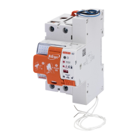
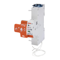
Graphical representation of RD/RD PRO device dimensions.
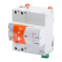
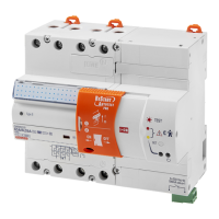
Graphical representation of RM/RM PRO device dimensions.
| Mounting | DIN rail |
|---|---|
| Number of poles | 2 |
| Mechanical durability | 20000 cycles |
| Electrical durability | 10000 cycles |
| Terminal type | Screw |