9
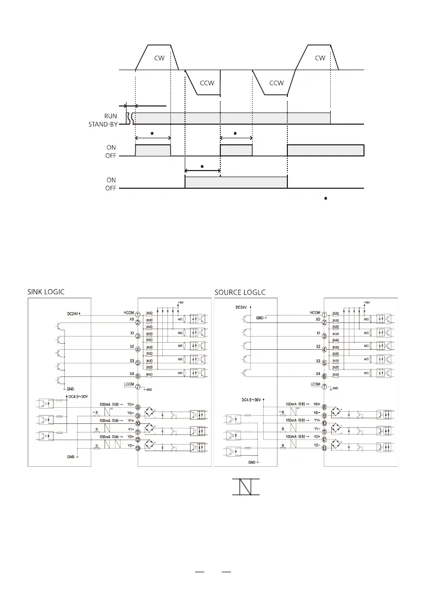
④ Timing chart example
※ Operation input
• The motor rotates when either FWD input or REV input is set to “ON”.
• The motor instantaneous stop when FWD input and REV input is set to “ON” at the
same time.
⑤ Connection example for I/O signals and programmable controller
This is connection example for operating a motor using a transistor output type
programmable controller.
Attention) For the Y0, Y1 and Y2, be sure to keep the current value at 100mA or less.
If the current exceeds this value, connect the limiting resistor R.
※ 1) Limited resistance
In the case of 24V DC : 680Ω~2.7Ω (2W)
In the case of 5V DC : 150Ω~560Ω (0.5W)
2) Twisted Pair
Shield Cable
Motor Movement
Operating Switch
50ms
or more
10ms or more
Drive
Programmable controller
Drive
Programmable controller
Deceleration
Stop
Deceleration
Stop
Deceleration
Stop
Instantaneous
Stop
FWD input
REV input
 Loading...