4
E. .02.1999 • G. 04.04.24
7 Technical data
8 Boiler connection measures
All measures in mm.
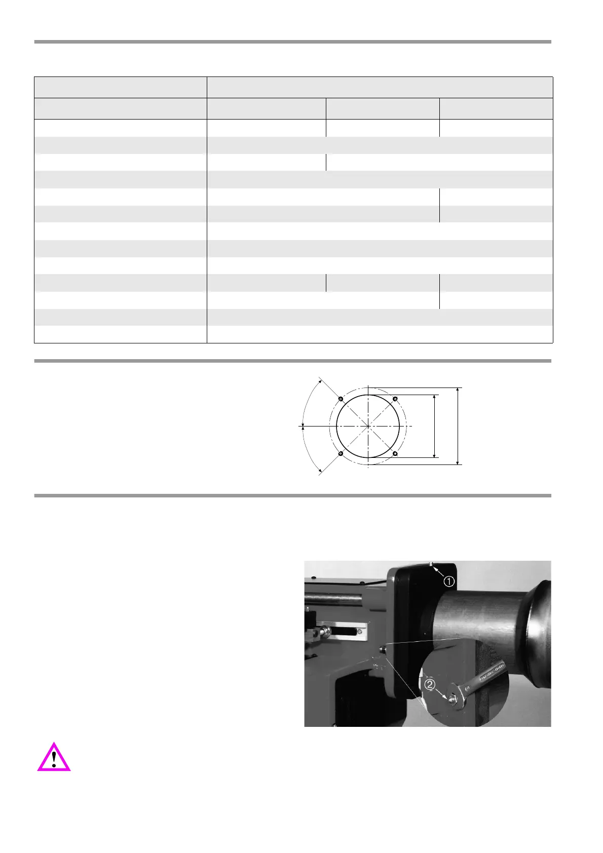
9 Installation of flange
The boiler connection plate must be prepared for the connection dimensions specified in "Boiler Connecti-
on Dimensions".The flange gasket can be used as a marking template.
First release the size 13 nuts (2) and the guide pin cap
nut. Now the burner flange and burner blast tube as-
sembly can be drawn forwards over the guide pin
.
If the door opening on the boiler is smaller than the dia-
meter of the burner blast tube, the burner blast tube
can be removed by rotating the bayonet fixing after re-
leasing the securing screw (1).
The threads of the fixing screws should be brushed
with graphite before fitting. Align flange and burner
blast tube assembly and tighten screws.
Boiler designs with a very low front plate or door, or boilers with inverted-flame burners require a
suitably extended mixer. If the oil burner was ordered with an extended mixer, this will already be
fitted.
Otherwise the short burner blast tube and nozzle assembly must be replaced with longer versions. The
standard extension is 100 mm.
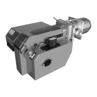
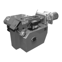
Burner type
Technical specifications M10-AE-WLE M10-Z-L-WLE M10.2-Z-L-WLE
Burner output in kW 120 - 355 125 - 490 255 - 566
Fuel oil EL, DIN 51603
Method of operation With start-up load reduction 2 Stage
Voltage 1 / N / PE ~ 50 Hz / 230 V
current consumption 4 A max. / 2 A eff. 6,5 A max. / 3,5 A eff.
Electric motor power (at 2800rpm) in kW 0.370 0.750
Oil pump (type) Danfoss BFP 52 / Suntec AT2 55 / Suntec AP 2
Flame failure controller QRB4
Control box LMO24
Weight in kg 25 26 27
Noise emission in dB (A) ≤ 71 ≤ 75
Emission class 2
NOx Limit value < 185 mg/kWh
 Loading...