5
E. .02.1999 • G. 04.04.24
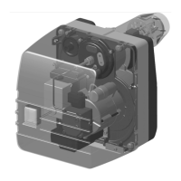
10 Inserting the Nozzle
After removing the two M8 nuts (size 13) the burner
can be drawn back on the guide pins. It is now in the
servicing position. Undo the screw and withdraw the
flame ring forwards.
Unscrew the plastic dust screw from the nozzle holder.
When doing so, it is essential to ensure that the sea-
ling face is not damaged.
Screw in the chosen nozzle using a size 16 Allen key.
Brace with an open-ended spanner. The flame ring is
then refitted and secured with the screw.
For burners with elongated burner tube
(100/200 mm), this is not possible.It has
the torches from the fire roombe screwed or removed.
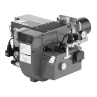
11 Adjustment of the ignition electrodes
The ignition electrodes are preset at the factory. The
gap between the nozzle and the ignition electrode
should be as shown in the diagram.
The dimensions are shown for checking purposes
after changing the nozzle.
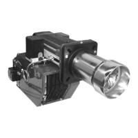
12 Adjusting the Nozzle Assembly (Dimension "A“)
The dimension "A" indicates the position of the nozzle
assembly and flame ring in the burner blast tube taper.
With the aid of the Adjustment Table the burner can be
preset according to the relevant output.
The nozzle holder setting should be such that the
pressure in front of the flame ring is approximately
5-6.5 mbar at level one and 9-10 mbar at level two.
In the case of boilers with a higher/lower furnace pres-
sure, dimension "A" has to be slightly increased / de-
creased.
The position of the cam on the air damper positioning
motor also has to be adjusted.
Higher resistance
➧
higher setting
Lower resistance
➧
lower setting
Precise adjustment to suit the specific system concerned is essential!
 Loading...