6
E. .02.1999 • G. 04.04.24
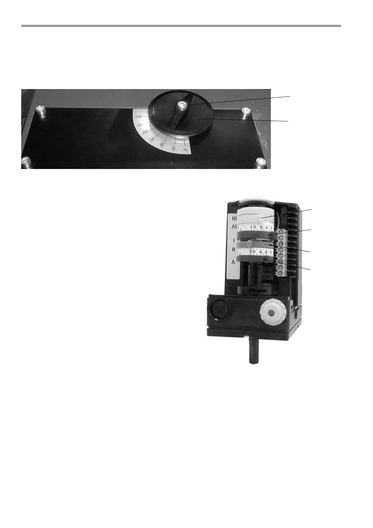
13 Air adjustment
Design -AE
After releasing the locking screw (1), the air volume is set to the required boiler output using the control
knob (2). The air damper position is given on the Adjustment Table.
When adjustment is complete, the securing screw (1) must be re-tightened.
Design -Z-L
The air damper positioning motor adjusts the air dam-
per position or trips the solenoid valve on two-stage
burners with air shut-off. Adjustment is via limit switch
cams on the positioning drive roller.
The cam positions for adjusting the burner to the requi-
red boiler output are given on the Adjustment
Table.
For this:
Remove cover from air damper positioning motor. Ad-
just cam positions using the lever or a conventional
screwdriver (cam holder fine adjuster).
If necessary, switching cams can be adjusted when
setting the burner.
Higher setting = More air, pressure increases
Lower setting = Less air, pressure decreases
Colour-coding of switch cams:
blue (II) = ST0 (Off position)
yellow (III/IV) = ST1 (Level 1 position)
red (V) = MV2 (solenoid valve
Level 2 position)
red (I) = ST2 (Level 2 position)
Please note the following when adjusting the switch cams:
- Do not set cam position for ST1 higher than ST2.
- Set cam position for MV2 to approx. 1/3 of the distance between Level 1 and Level 2.
- Check cam position for MV2 after correcting cam position for ST1.
- After adjusting ST1 and ST2 you have to switch to the next stage in order to activate the new setting.
- When adjustment of the burner is complete, refit positioning motor cover and set level selector switch to
position for Level 2.
Important
Do not set the cam position by means of the marking 88.
 Loading...